Intelligent valves- Control valves with integrated energymeasurement
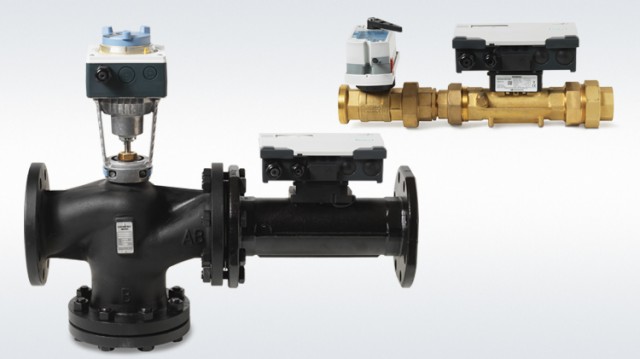
Intelligent Valve – control valve with integrated energy data acquisition for ventilation and air conditioning plants as well as precontrol circuits. Sensor guided dynamic flow control.
- Threaded valves EVG4U10E..:
– DN 15…50
– Nominal volume flow 1.5…18 m3/h
– Externally threaded connection per ISO-228 - Flanged valves EVF4U20E..:
– DN 65…125
– Nominal volume flow 30…120 m3/h
– Flange connection per ISO 7005-1 - System integration in building control technology over BACnet IP
- Supports the direct transfer to Siemens Building Operator
- Ultrasonic volume flow measurement at measuring accuracy ± 2 %
- Temperature measurement with paired immersion temperature sensors
Use
The Intelligent Valve is a 2-port pressure-independent control valve (PICV) with volume flow, temperature and power measurement for heating, ventilation, and air conditioning plants.
The valve can be integrated as analog (DC 0/2…10 V or 4…20 mA) or digital (BACnet IP) into the temperature control circuit. All process data (volume flow, power, primary flow and return temperature, etc.) can still be read out digitally even if integrated as analog. The Intelligent Valve also has local limitation and optimization functions that support energy efficient plant operation.
In addition to digital integration in the building automation and control system, integration in the cloud with the Siemens Building Operator app supports the building operator to operate and monitor the system as well as evaluate energy consumption.
The Intelligent Valve 4 applications:
- Dynamic control valve
- Differential pressure controller
- Flow temperature controller
- Outside temperature-dependent flow temperature controller
The functions for volume flow limitation and energy acquisition are available at any time in all 4 applications.
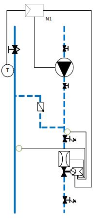
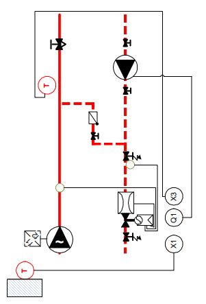
Intelligent Valve as dynamic control valve
In this application, the Intelligent Valve is part of a temperature control circuit and receives a setpoint from a superposed automation station that it interprets, depending on the control type, as valve position, volume flow, or output and controls accordingly.
The example to the right depicts this based on a precontrol circuit for chilled ceilings.
Automation station N1 controls the flow temperature of the chilled ceiling circuit by demand and specifies the setpoint of 0…100 % on the Intelligent Valve. This can occur in analog (0…100 % = DC 0…10 V) form or remotely over BACnet IP.
The Intelligent Valve follows this setpoint and sets, for example in volume flow control mode, the appropriate volume flow.
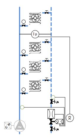
Intelligent Valve as differential pressure controller
The Intelligent Valve can act as a differential pressure
controller for a section of the plant.
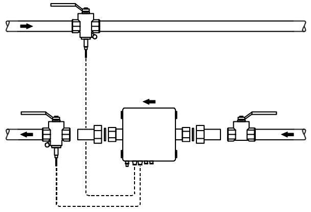
In this application, the Intelligent Valve controls independently of an automation station. Using an auxiliary differential pressure sensor [X3], it acquires the present differential pressure in the plant section and adjusts the valve position resulting in a constant differential pressure.
In this application, the Intelligent Valve does not receive an external setpoint, but rather controls to a fixed local setpoint that the user sets with ABT Go.
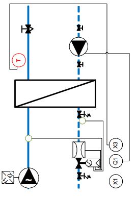
Intelligent Valve as flow temperature controller without outside air temperature sensor
In this application, the Intelligent Valve assumes the role of the automation station.
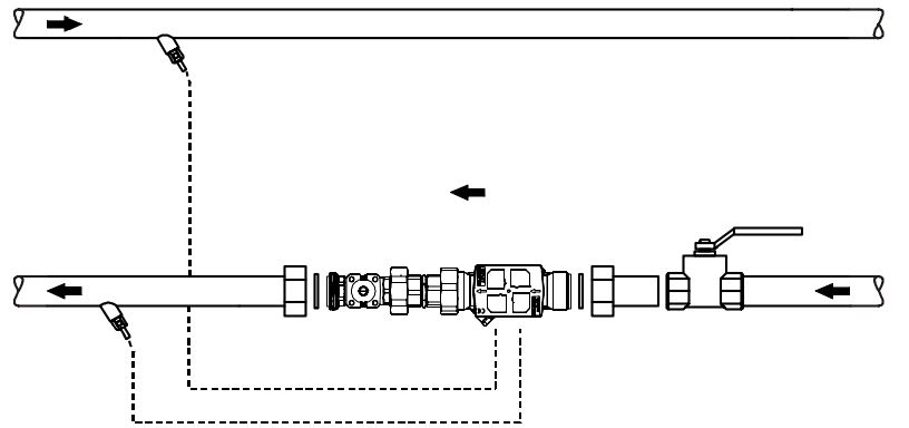
Using an auxiliary secondary flow temperature sensor [X3], it acquires the flow temperature and controls to the present temperature setpoint by adjusting the volume flow.
The temperature setpoint can either be fixed (ABT Go) or preset externally (remote or analog).
Intelligent Valve as weather-dependent flow temperature control
The Intelligent Valve can control the valve in a heating group to a flow temperature based on the weather. In this application, the Intelligent Valve assumes the role of the automation station.
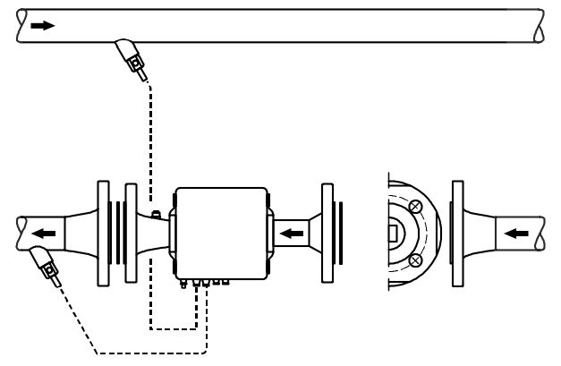
In weather-dependent control, the flow temperature [X3] isassigned to the prevailing outside air temperature [X1] via the heating curve.
The secondary flow temperature sensor [X3] acquires the present flow temperature and the Intelligent Valve controls it to the formed flow temperature setpoint by adjusting the volume flow.
In addition to the heating curve, a weekly timeswitch can also preset the room operating mode (Comfort, PreComfort, Economy, Protection).
The heating curve and the weekly scheduler are set in ABT Go. The heating circuit pump can be released or locked with relay Q1.
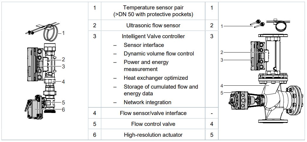
Technical design
Basic design
The Intelligent Valve combines four main functions:
- Exact, continuous volume flow measurement with an ultrasonic flow sensor
- Precise temperature measurement using paired Pt1000 temperature sensors
- Precise volume control using a control valve with a high-resolution actuator
- Dynamic hydraulic balancing, power and energy calculations, storage of cumulated flow and energy data as well as network integration via a central control unit
Volume flow is acquired continuously in the ultrasonic flow sensor and provided to the Intelligent Valve controller, where the controller applies it as the actual value for control or limitation by guiding the control valve position until the volume flow actual value for the applicable setpoint is achieved.
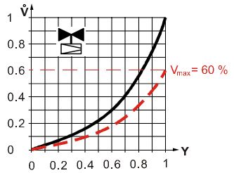
3 characteristic curves are available:
Equal percentage, optimized in the opening range (factory setting) Recommended for heating and cooling registers,
where the transfer characteristic is unknown.
![]() :Modified characteristic curve with volume
:Modified characteristic curve with volume
flow maximum limitation at 60 %
Linear
Recommended for plate heat exchangers water/water
or injection circuits in precontrol circuits.
![]() :Cut characteristic at the volume flow
:Cut characteristic at the volume flow
minimum limitation
Heat exchanger optimized
Recommended for heating and cooling registers,
where the transfer characteristic (a-value) is known
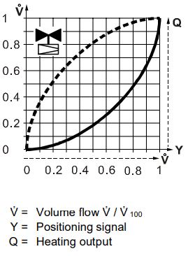
![]() :Q = f(V) Heat exchanger characteristic
:Q = f(V) Heat exchanger characteristic
![]() :Q = V = f(Y) Flow characteristic for Intelligent
:Q = V = f(Y) Flow characteristic for Intelligent
Valve
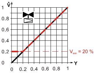
In the event of volume flow maximum limitation, the curve always adapts to the entered limitation setpoint (example for equal percentage curve).
During volume flow minimum limitation, the characteristic is cut off below the minimum flow (example for a linear characteristic curve).
Position control
The control valve position is proportional to the setpoint (setpoint 0 % = closed; setpoint 100 % = H100) – whereby the limitation to the applicable maximum volume flow (V̇100 or V̇max) remains active.
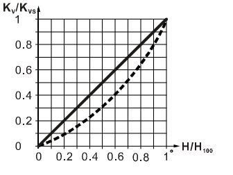
Dynamic volume flow control is inactive in position control mode and the kVS valve characteristic curve is not electronically modified.
The kVS valve characteristic curve is derived by combining the control valve or control ball valve characteristic and the resistance characteristic of the flow sensor.
This results in an equal percentage kVS valve characteristic curve with a ngl 2.2 for valves with a threaded connection EVG..; the kVS valve characteristic curve for flanged valves EVF.. is nearly linear.
Output control
The design output is the reference variable. It is defined by:
- Design volume flow V̇max
- Design temperatures TVL, design and TRL, design
Design output = c × design volume flow × difference of the design temperatures Q̇design ~ V̇max × (TVL, design – TRL, design) whereby Q̇max is the output limitation in %, relating to the design output of the consumption (heat exchanger/precontrol circuit).
The setpoint for the output for control is interpreted by referencing the output limitation – (Y = 0…100 % Q̇max; 0 % = closed; 100 % = Q̇max),
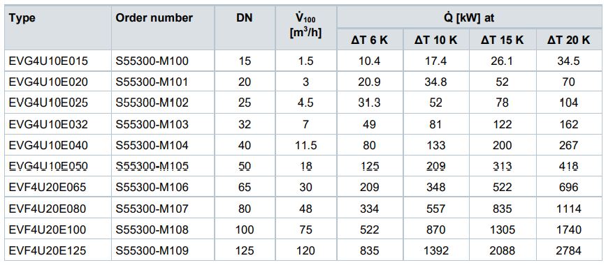
The “Sizing” section provides a table of the output values for water at typical temperature differences (Sizing as dynamic control valve [➙ 7]).
The volume flow maximum limitation (V̇100 or V̇max) also remains active in the output control mode. In output control, the dynamic volume flow control is inactive, since any undesired change in volume flow automatically results in a change in output, which is controlled anyway.
The flow characteristic curve is not relevant to output control.
Operating limits
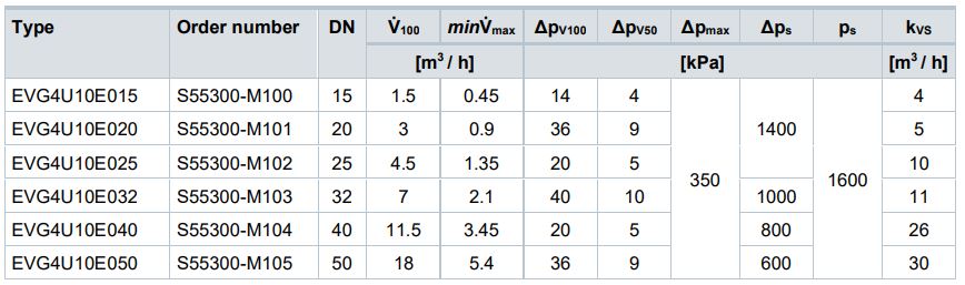
Nominal volume flow and minimum required differential pressure – the Intelligent Valve has, as does any dynamic PICV, a nominal flow V̇100 by build design that may not be exceeded during operation. A minimum differential pressure (Δpmin) is required to achieve nominal volume flow; it is calculated from the Intelligent Valve kvs value. In contrast to mechanical PICVs, the electronic volume flow control on the Intelligent Valve remains active below the minimum differential pressure – so that the network is always optimally balanced.
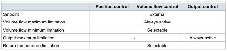
The Intelligent Valve supports different limitation functions:
- Volume flow maximum limitation
- Volume flow minimum limitation
- Output maximum limitation
- Return temperature min./max. limitation
Volume flow maximum limitation
We recommend activating the volume flow maximum limitation if the design volume flow for the partial plant (heating coil/cooler/precontrol circuit) as controlled by the Intelligent Valve, is lower than the nominal flow of the Intelligent Valve. In volume flow control mode, the set volume flow V̇max – which can be anywhere between 30…100 % of the nominal volume flow – is interpreted as the 100 % setpoint. It only serves as the limitation value in the other control types
Volume flow minimum limitation
The volume flow minimum limitation achieves a minimum flow through the controlled partial plant where this appears to be appropriate. The limitation is of course pressure independent so that there is no over or under supply as the local differential pressure changes.
Output maximum limitation
In contrast to volume flow limitation, the output limitation adapts dynamically to the temperature distribution in the plant. As a consequence, output control is more suitable for critical users than volume flow limitation.
Return temperature min./max. limitation
Modern, high-efficiency output generators must have sufficient low/high return temperatures to achieve their output numbers/degree of efficiency. With Intelligent Valve, you can precisely limit the return temperature value as needed by the given plant.
- A return temperature maximum limitation is available if the Intelligent Valve is used in a heating application; a return temperature minimum limitation is available in a cooling application. The setting is made in two steps:
Enable function - Set limitation setpoint
– Factory setting for maximum limitation = 40 °C
– Factory setting for minimum limitation = 10 °C
Not all limitations are available to each control type. The following limitations are available based on control type:
Sizing
Sizing as dynamic control valve
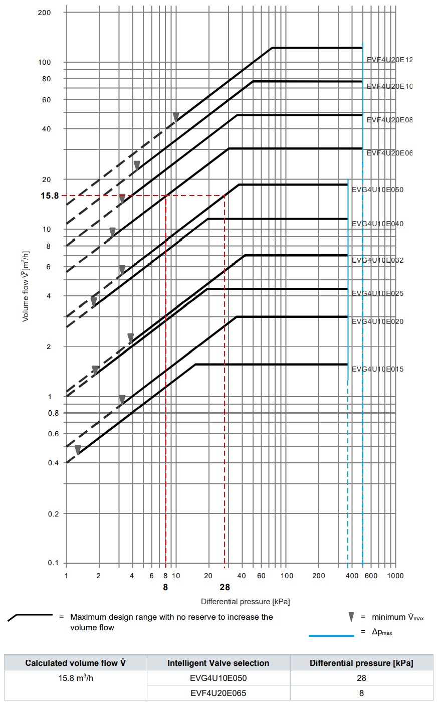
As a pressure-independent solution, it is generally easy to size the Intelligent Valve. If the volume flow is already a known variable, simply select the corresponding valve from the diagram below. The electronic volume flow controller ensures that the valves always achieve the specific nominal volume flow. The nominal volume flow cannot however be exceeded.
We recommend selecting the valves so that the maximum volume flow V̇max must be preset to a value of 30…90 %. Just in case that a somewhat higher volume flow is required during installation than was originally calculated.
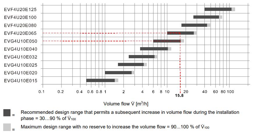
Maximum consumer output range at typical temperature differences:
Sizing as flow temperature controller
As a rule, the output for transmission in this application is available at the indicated primary design temperatures as design variables.
This information can be used to calculate the required plant design volume flow which then influences the valve selection. See Engineering examples [➙ 9].
Sizing as differential pressure controller
4 design parameters are required for the design as differential pressure controller:
- The differential pressure Δpw to control; it may be between 25…120 kPa.
- The minimum pending total differential pressure Δptotal, min
- The maximum pending total differential pressure Δptotal, max
- The design flow V̇Plt for the section of the plant controlled by the Intelligent Valve
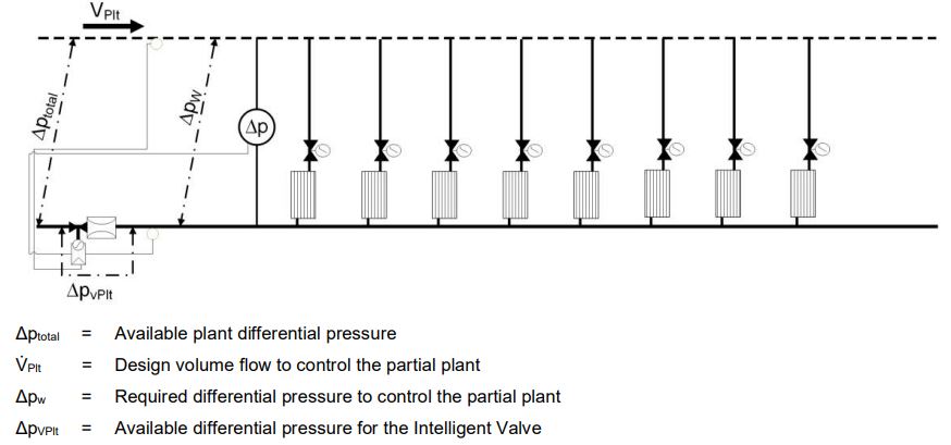
In an initial step, the minimum differential pressure available to the Intelligent Valve is calculated:
ΔpVPlt = Δptotal, min – Δpw
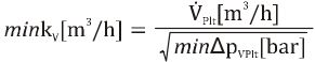
The minimum required kV value for the Intelligent Valve can be determined using the ΔpVPlt and the design flow V̇Plt :
min kv = V̇Plt / √(ΔpVPlt)
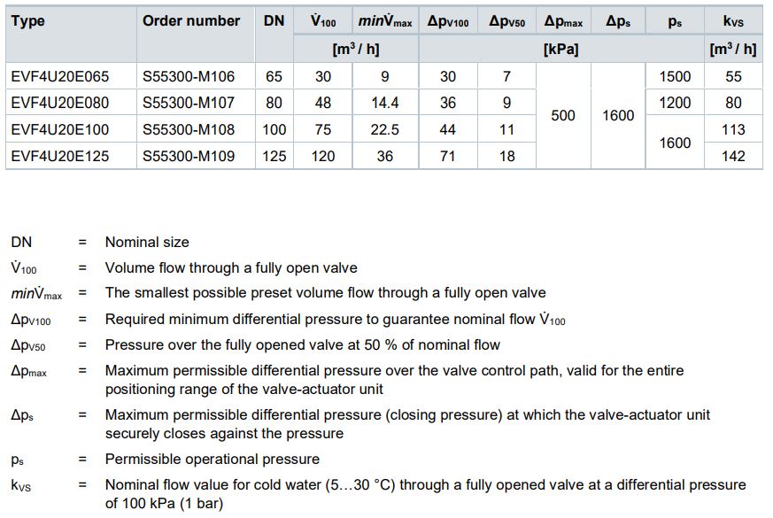
Select the valve with the next higher kVS value from the Type summary [➙ 12].
Engineering examples
Intelligent Valve as dynamic control valve or flow temperature controller
Calculation basis
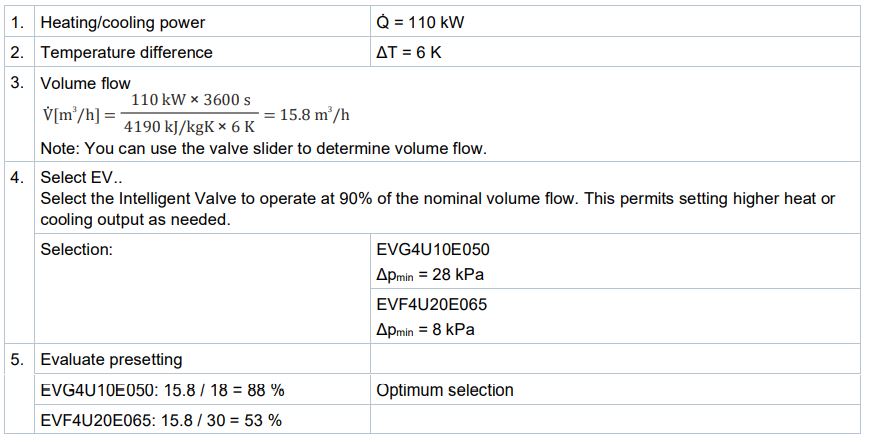
- Determination of heating or cooling demand Q̇ [kW]
- Determination of temperature difference ΔT [K]
- Calculation of volume flow
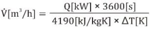
- Select the suitable Intelligent Valve EV..
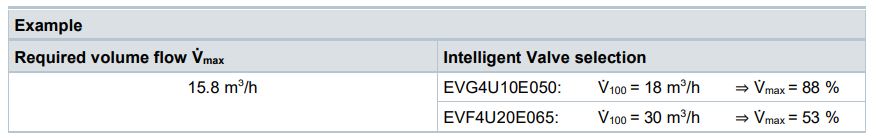
Example
Intelligent Valve as differential pressure controller
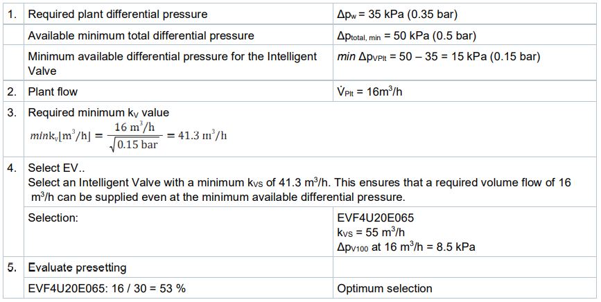
Calculation basis
- Determination of the minimum available differential pressure for the Intelligent Valve min ΔpVPlt [kPa]
- Determination of the plant flow V̇Plt [m3 /h]
- Calculation of the minimum required kV value
- Select a suitable Intelligent Valve EV..: kVS > min kV
Example
Sizing diagram
You can rely on the kvs value under Type summary (page Type summary [➙ 12]) to determine the pressure drop at the requested maximum volume flow.
Type summary
Threaded Intelligent Valve EVG4U10E..
Flanged Intelligent Valve EVF4U20E..
Scope of delivery
The Intelligent Valve is supplied as a complete set consisting of:
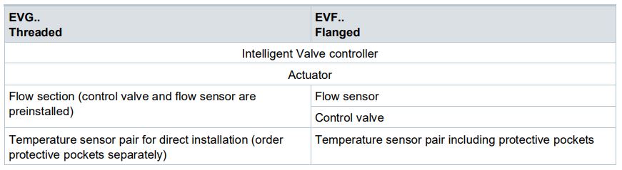
The devices are supplied without fittings, mating flange, and gaskets.
Welding sleeves, e.g. WZT-G12, for protective pockets must be ordered separately!
Accessories/spare parts
Accessories
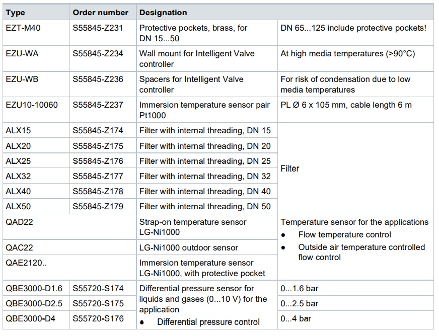
Spare parts
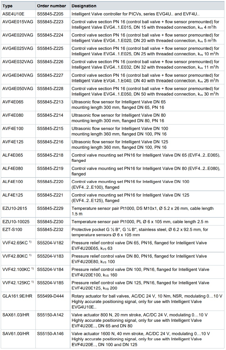
Only available as spare part for EVF4U20E..
Product documentation
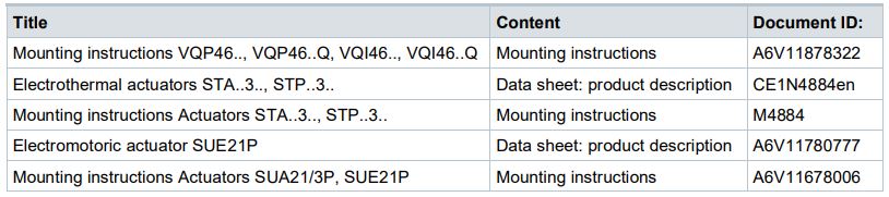
Related documents such as environmental declarations, CE declarations, etc., can be downloaded at the following Internet address: http://siemens.com/bt/download
Notes
Safety notes
Comply with the following safety notes to protect life, limb, and property.
The safety notes in the document include the following elements:
- Symbol for hazard
- Signal word
- Type and source of hazard
- Consequences in the event the hazard occurs
- Measures or prohibitions to prevent the hazard
Symbol for hazard
This is the symbol for hazard. It warns you of Risks of injury.
Comply with all measures designated by this symbol to prevent injury or death
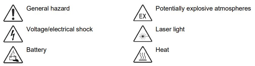
Additional hazard symbol
These symbols indicate general hazards, type of hazard, possible consequences, measures and prohibitions, a sample of which is displayed in the following table:
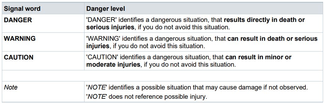
Signal word
The signal word classifies the hazard as defined in the following table:
Depiction of risk of injury
Notes on risk of injury is depicted as follows:
WARNING
Type and source of hazard
Consequences in the event the hazard occurs
● Measures/prohibitions to prevent the hazard
DEPICTION for possible damage to property
Notes on possible damage to property is depicted as follows:
NOTICE
Type and source of hazard
Consequences in the event the hazard occurs
● Measures/prohibitions to prevent the hazard
Safety
CAUTION
National safety regulations
Failure to comply with national safety regulations may result in personal injury and property damage.
● Observe national provisions and comply with the appropriate safety regulations.
Qualified personnel
NOTICE
Qualified personnel!
Improper installation may override safety measures that a lay person may not recognize.
● Specialized knowledge of heating and air conditioning plants is required for installation.
● Only properly trained personnel may install the equipment.
● Prevent access to lay persons, especially children.
Only persons who can be reasonably expected to reliably conduct the work may actually perform the tasks. Do not permit persons whose reactions may be impaired, for example, by drugs, alcohol, or medications to perform the tasks.
Heating specialist
Heating specialists are persons who are capable of performing the mechanical work on heating and air conditioning plants and to independently recognize and avoid hazards due to their technical training, knowledge and experience as well as their knowledge of applicable standards and regulations.
Heat specialists are specially trained for the work environment where they are active and know the relevant standards and regulations.
Engineering
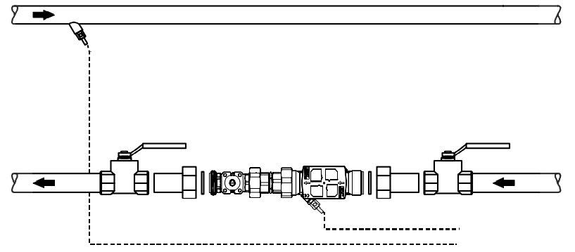
An unhindered inlet section of L ≥ 5 x DN must be maintained upstream of the flow sensor to guarantee the indicated measurement and control accuracy.
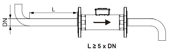
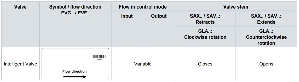
The indicated flow direction (arrow on the flow sensor and valve body) must be correct; the
Intelligent Valve cannot otherwise be operated!
Do not install it at the highest point on the partial plant since air bubbles may otherwise collect in the flow meter.
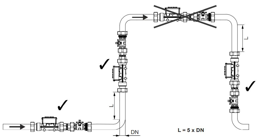
The rule is: Measure first, then control – in other words, the flow sensor must always be mounted upstream of the control valve in a compact installation.
The Intelligent Valve must be installed in the return for optimum performance. The components are subject to less wear and tear due to the lower temperatures.
We recommend installing a filter or strainer, e.g. ALX.., in the flow to the heat exchanger.
This increases the reliability and life cycle of the Intelligent Valve.
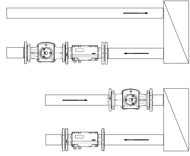
The flow sensor and control valve can be installed separately:
Threaded versions: In general, note that the torque of the threading is very high (75…500 Nm).
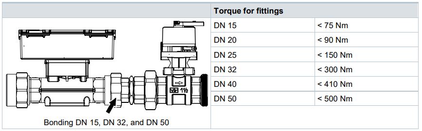
NOTICE
DN 15, DN 32, and DN 50
Please note that the insertion part of the fitting is bonded to the flow sensor and cannot beremoved!
● The fitting must remain on the flow sensor.
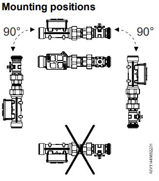
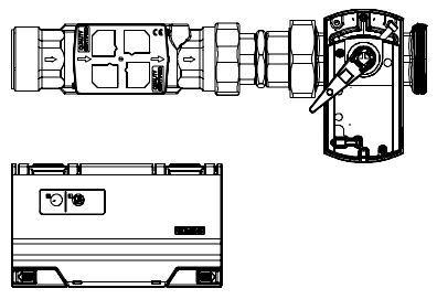
Mounting
The Intelligent Valve is assembled at the mounting location. No adjustments, with the exception of configuring with the ABT Go app (see Commissioning [➙ 22]) nor special tools are required. Separate mounting instructions are included with the valve and flow sensor.
Mount the flow sensor in the return if the media temperatures exceed 90 °C. If not possible, mount the Intelligent Valve controller remotely from the flow sensor and use the wall-mount plate EZU-WA.
Mounting the temperature sensors Threaded valves EVG4U10E..
The EVG.. threaded valves are supplied with direct immersion temperature sensors EZU10- 2615.
The sensors with the M10x1 threaded connection can be directly immersed in the flowsensor. The second temperature sensor is also directly immersed with the WZT-G10 welding sleeve (available as accessory).
As an alternative, the sensors can be immersed directly in off-the-shelf ball valves with integrated measuring points (e.g. Siemens WZT-K.. / Jumo 902442/11) or t-pieces (e.g. Jumo 902442/31).
The brass protective pockets EZT-M40 are available for mounting with protective pockets.
Flanged valves EVF4U20E..
The EVF.. flanged valves include the temperature sensors EZU10-10025 for installing in theprotective pockets EZT S100 (also included).
Welding sleeves must be planned on the construction side (e.g. WZT-G12) – Installation example with protective pocket.
Commissioning
The device has only a simple user interface.
Siemens ABT Go app is used to actually commission the device.
ABT Go App (Version 3.3.1 or later)
The Siemens ABT Go app is available in iOS and Android versions in the corresponding app stores and can be used on smartphones and tablets. It connects directly over WLAN. The Intelligent Valve’s own WLAN button activates the device’s WLAN access point.
The following are the most important setting parameters for commissioning the Intelligent Valve:
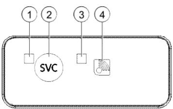
User interface on the device
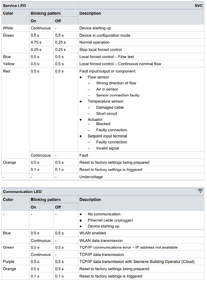
Service LED [1]
- Indicates the operating state (see table
below)
Service button [2]
- Override setpoint and set V̇100 for 10
minutes (press for 3…6 s) - Start flow test (press for 6…8 s)
Communication LED [3]
- Indicates the communication state (see
table below?
WLAN button [4]
- Enable integrated WLAN Access Point for 10 min (press for ca. 0.5 s)
- Reset device to factory settings
- Press both buttons ([2], [4]) at the same time for 10…15 s: The LEDs ([1], [3]) slowly flash orange for 10 s You can cancel the process during these 10 seconds by releasing the buttons.
- After flashing for 10 s, the LEDs flash quickly for ca. 5 s and the reset is triggered by releasing the buttons.
- The controller returns to normal operation without resetting if you continue to press the buttons.
NOTICE
All configurations, network settings, commissioning parameters, and passwords are set to factory settings!
● This action cannot be cancelled nor reversed.