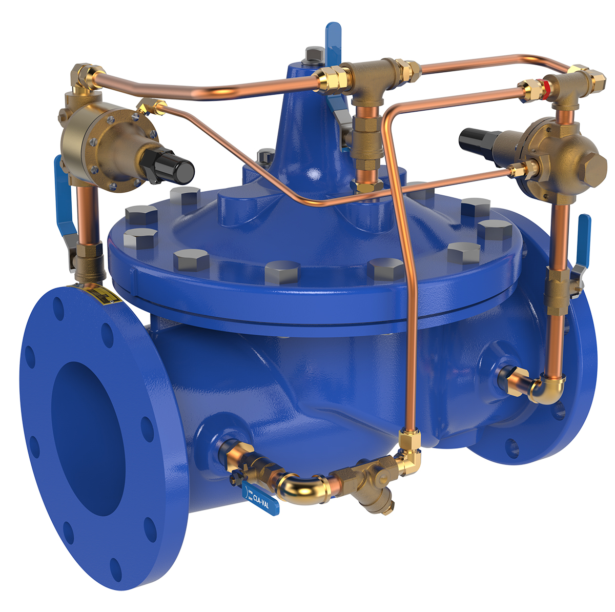
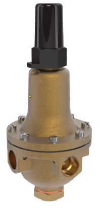
Combination Pressure Reducing and Surge Control Valve
Product Advantages
- Sensitive and Accurate Pressure Control
- Easy Adjustment and Maintenance
- Optional Check Feature
- Fully Supported Frictionless Diaphragm
The Cla-Val Model 94-01 Combination Pressure Reducing and Surge Control Valve automatically reduces a higher inlet pressure to a steady lower downstream pressure, regardless of changing flow rate and/or varying inlet pressure. This valve is an accurate, pilot-operated control valve capable of holding downstream pressure to a pre-determined limit. When downstream pressure rapidly exceeds the pressure setting of the pressure reducing control pilot, the surge pilot (CRL-60) will open quickly to prevent a rapid pressure rise downstream.
If a check feature is added, and a pressure reversal occurs, the downstream pressure is admitted in the main valve cover chamber closing the valve to prevent return flow.
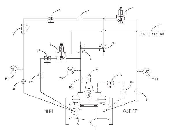
Schematic Diagram
Item Description
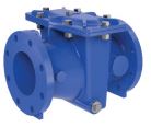
1. 100-01 Hytrol Main Valve
2. X58C Restriction Assembly
3. CRD Pressure Reducing Control
4. CRL-60 Pressure Relief Contro
Optional Features
Item Description
A. X46A Flow Clean Strainer
B. CK2 Isolation Valve
C. CV Flow Control (Closing)*
D. Check Valves with Isolation Valve
F. Remote Pilot Sensing
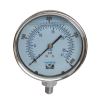
P. X141 Pressure Gauge
S. CV Speed Control (Opening)
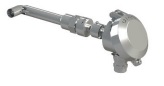
V. X101 Valve Position Indicator
Y. X43 “Y” Strainer
*The closing speed control (optional) on this valve should
always be open at least three (3) turns off its seat.
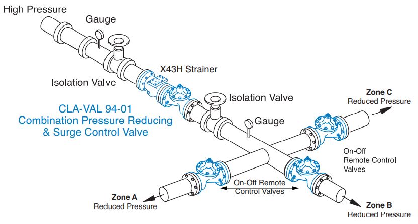
Typical Application
Should the downstream pressure suddenly increase above the setting of the pressure reducing control due to on-off operation of two or more downstream systems, the Surge Control tracks rapidly enough to prevent high pressure surges from entering any of the downstream systems, when any one of the downstream systems is rapidly closed off. The typical combination pressure reducing and surge control valve station uses Model 94-01 to control surges in downstream piping as remote control valves change from one downstream
zone to another. Surge Control is set approximately 10 psi above Pressure Reducing Control to prevent high
pressure surge entering other downstream zones.
Model 94-01 (Uses 100-01 Hytrol Main Valve)
Pressure Ratings (Recommended Maximum Pressure – psi)
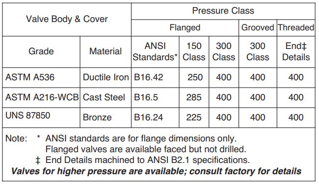
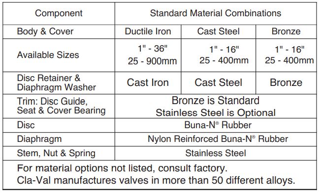
Materials
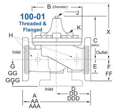
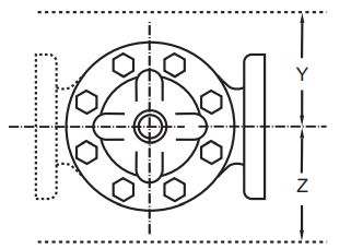
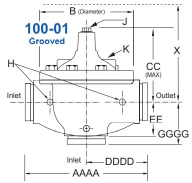
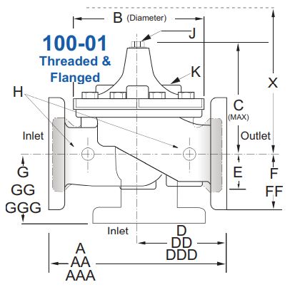
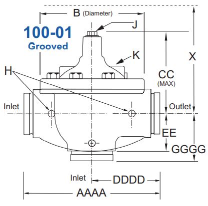
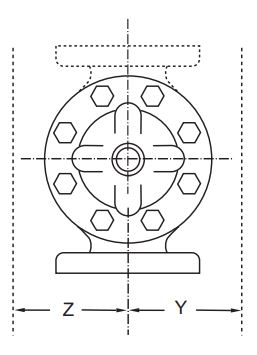
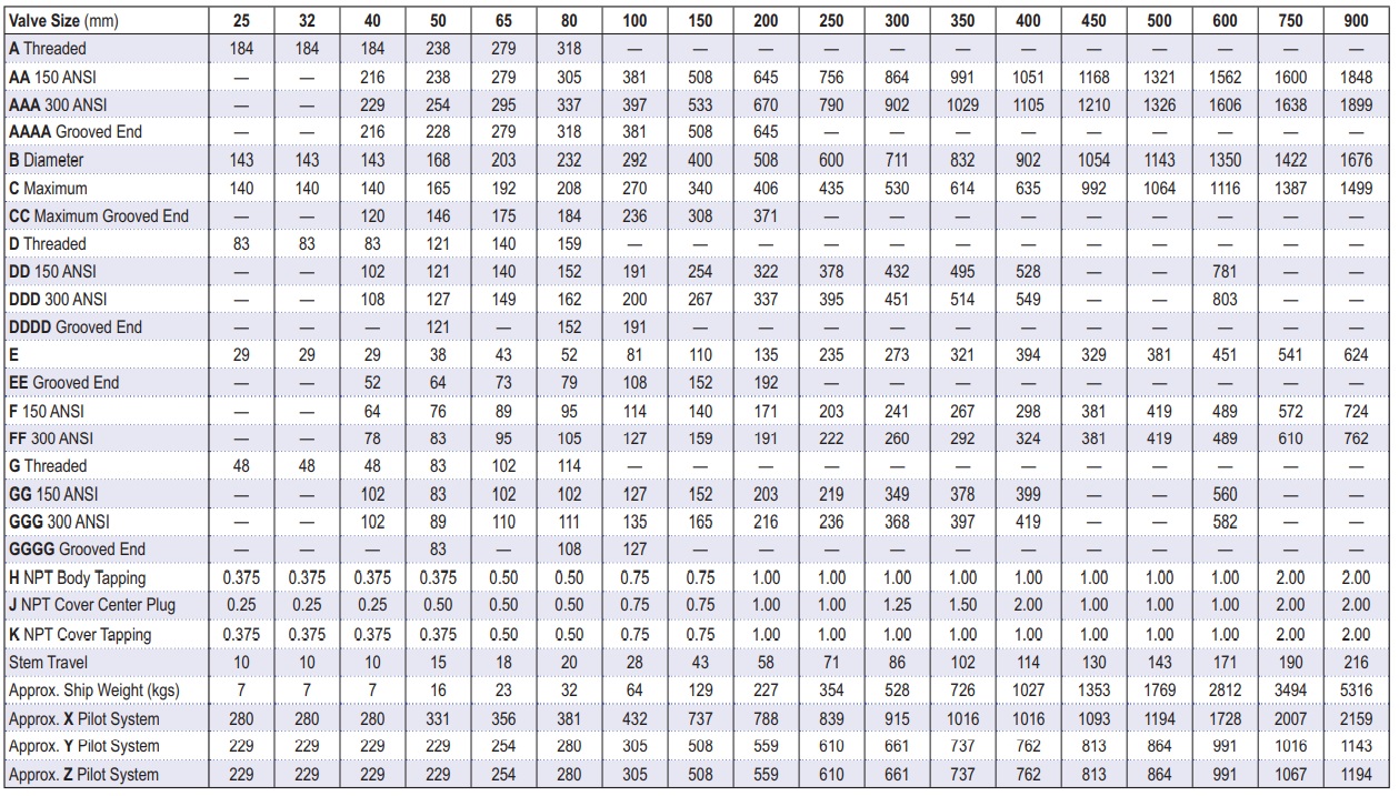
Model 94-01 Dimensions (In Inches)
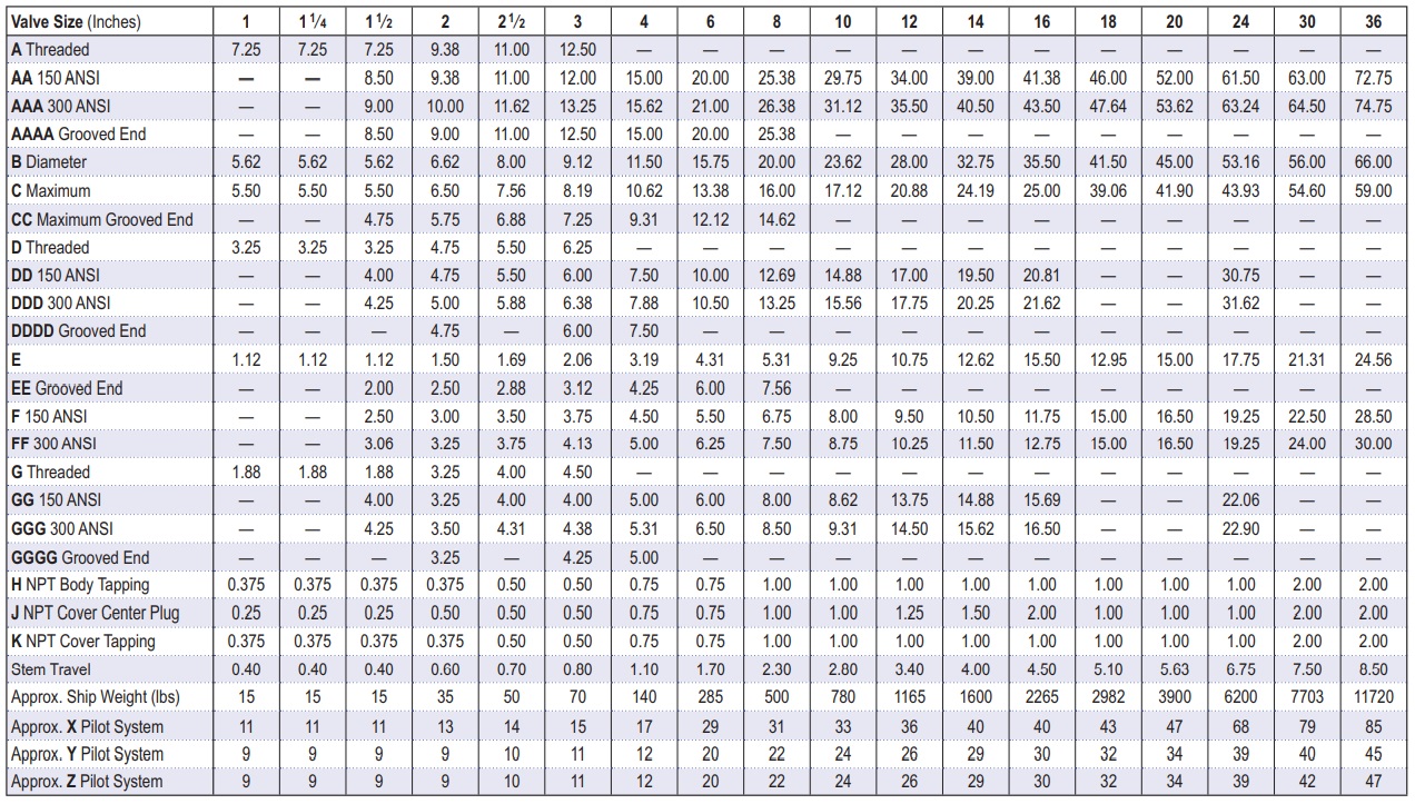
Model 94-01 Metric Dimensions (Uses 100-01 Hyrol Main Valve)
Valve Options
X141 Pressure
Gauge
X101AR Valve
Position Indicator
with Air Release
X101
Valve Position
Indicator
X144 e-FlowMeter
X43H
Strainer
X43H
Strainer
Stainless
Steel Pilot
94-01 Dimensions (In mm)
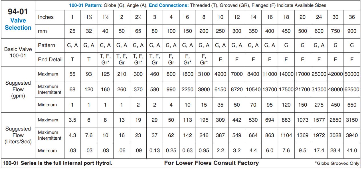
Many factors should be considered in sizing pressure reducing valves including inlet pressure, outlet pressure and flow rates. For sizing questions or cavitation analysis, consult Cla-Val with system details.
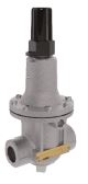
CRD Pressure Reducing Pilot Control
The CRD Pilot is held open by the force of the compression spring above the diaphragm, and closes when the downstream pressure acting on the underside of the diaphragm exceeds the spring setting. The CRD senses downstream pressure directly.
Flow through the control responds to changes in downstream pressure. Turning the adjusting screw clockwise increases the delivery pressure. Turning it counterclockwise decreases the pressure. A resilient disc assures tight shut-off on dead-end service.
See the E-CRD E-heet for more details.
CRL-60 Pressure Relief Pilot Control
The Model CRL-60 is normally held closed by the force of the compression spring above the diaphragm. Control pressure is applied under the diaphragm. When the controlling pressure exceeds the spring setting, the disc is lifted off its seat, permitting flow through the control. When control pressure drops below the spring setting, the spring forces the control back to its normally closed position. The controlling pressure is
applied to the chamber beneath the diaphragm through a sensing port on the CRL-60 body.
See the E-CRL-60 E-Sheet for more details
Pilot System Specifications
Adjustment Ranges
CRD CRL-60
2 to 30 psi 0 to 75 psi
15 to 75 psi 20 to 105 psi*
20 to 105 psi 20 to 200 psi
30 to 300 psi* 100 to 300 psi
*Supplied unless otherwise specified
Other ranges available, please consult factory.
Temperature Range
Water: to 180°F
Materials
Standard Pilot System Materials
Pilot Control: Low Lead Bronze
Trim: Brass & Stainless Steel Type 303
Rubber: Buna-N® Synthetic Rubber
Optional Pilot System Materials
Pilot Systems are available with optional
Stainless Steel or Monel materials.
Note: Available with remote sensing control.
When Ordering,
Specify:
1. Catalog No. 94-01
2. Valve Size
3. Pattern – Globe or Angle
4. Pressure Class
5. Threaded or Flanged
6. Trim Material
7. Adjustment Range
8. Desired Options
9. When Vertically Installed