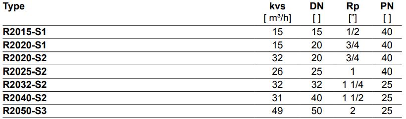
Type overview
Technical data
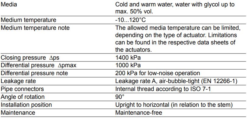
Functional data
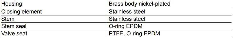
Materials
Safety notes
- The valve has been designed for use in stationary heating, ventilation and air-conditioning systems and is not allowed to be used outside the specified field of application, especially in aircraft or in any other airborne means of transport.
- Only authorised specialists may carry out installation. All applicable legal or institutional installation regulations must be complied during installation.
- The valve does not contain any parts that can be replaced or repaired by the user.
- The valve may not be disposed of as household refuse. All locally valid regulations and requirements must be observed.
- When determining the flow rate characteristic of controlled devices, the recognised directives must be observed.
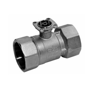
Product features
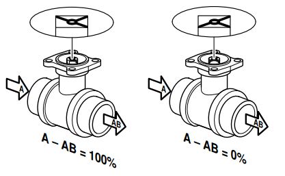
Mode of operation
The open-close ball valve is adjusted by a rotary actuator. The rotary actuator is connected by an open-close signal. Open the ball valve counterclockwise and close it clockwise.
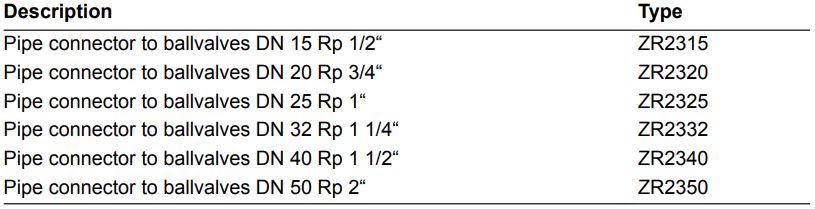
Accessories
Mechanical accessories
Installation notes
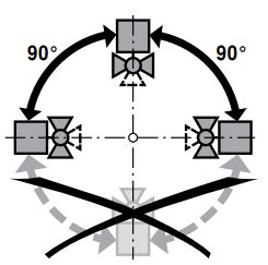
Recommended installation positions
The ball valve can be installed upright to horizontal. The ball valve may not be installed in a hanging position, i.e. with the stem pointing downwards.
Water quality requirements
The water quality requirements specified in VDI 2035 must be adhered to. Belimo valves are regulating devices. For the valves to function correctly in the long term, they must be kept free from particle debris (e.g. welding beads during installation work). The installation of suitable strainer is recommended.
Maintenance
Ball valves and rotary actuators are maintenance-free. Before any kind of service work is carried out on the actuator, it is essential to isolate the rotary actuator from the power supply (by unplugging the electrical cable). Any pumps in the part of the piping system concerned must also be switched off and the appropriate slide valves closed (allow everything to cool down first if necessary and reduce the system pressure to ambient pressure level). The system must not be returned to service until the ball valve and the rotary actuator have been properly reassembled in accordance with the instructions and the pipeline has been refilled in the proper manner.
Flow direction
The direction of flow, specified by an arrow on the housing, is to be complied with, since otherwise the ball valve could become damaged. Please ensure that the ball is in the correct position (marking on the spindle).
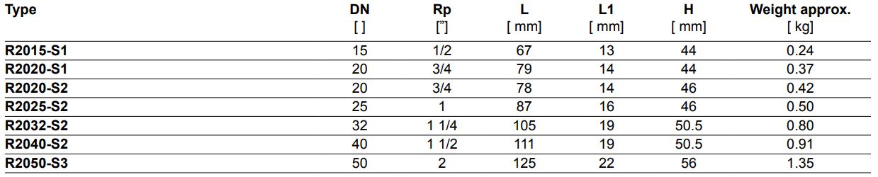
Dimensions [mm]
Dimensional drawings
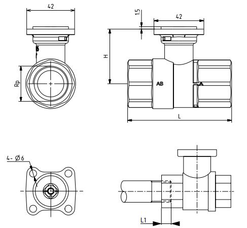
L1: Maximum screwing depth.
The actuator dimensions can be found on the
respective actuator data sheet.