Fire Protection Float Valve
Product Advantages
- Accurate and Repeatable Level Control
- On-Off or Non-Modulating Action
- Fully Adjustable High and Low Level Settings
- Simple Design, Proven Reliable
- Easy Installation and Maintenance
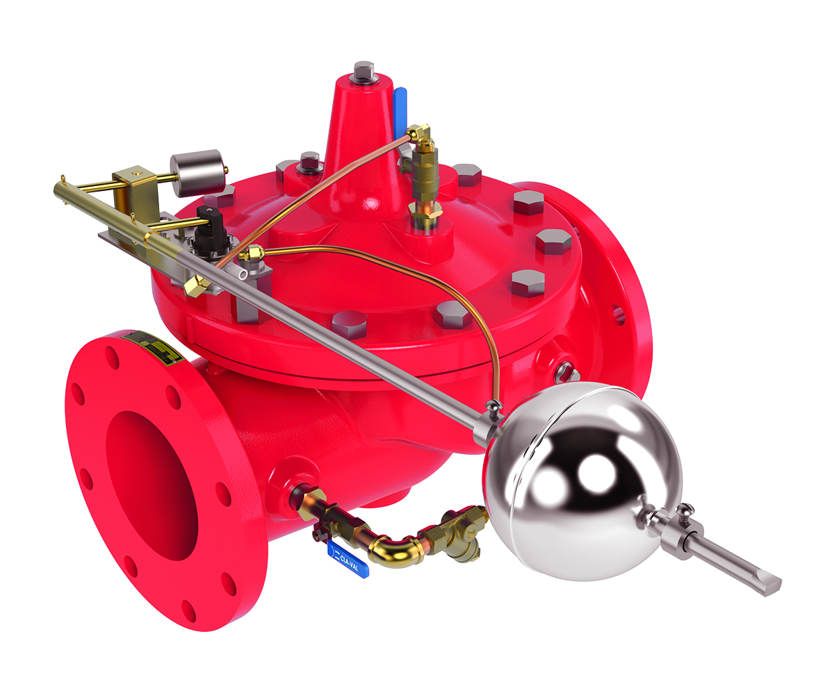
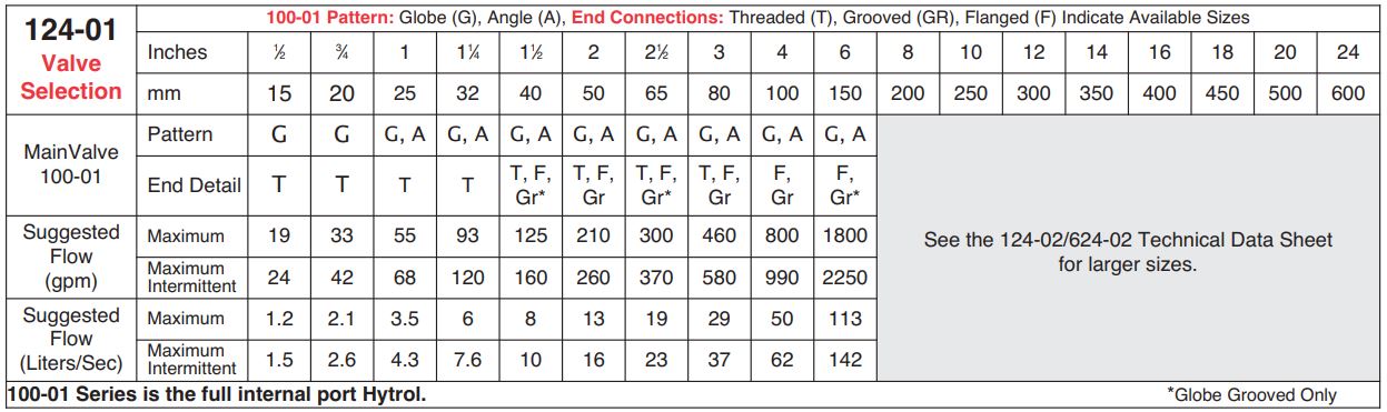
The Cla-Val Model 124-01/624-01 Float Valve is a non-modulating valve that accurately controls the liquid level in tanks. This valve is designed to open fully when the liquid level reaches a pre-set low point and close drip-tight when the level reaches a preset high point.
This is a hydraulically operated, diaphragm valve with the pilot control and float mechanism mounted on the cover of the main valve. The float positions the pilot control to close the valve when the float contacts the upper stop. The high and low liquid levels are adjusted by positioning the stop collars on the float rod. The difference between high and low levels can be adjusted to as little as one inch, or to as much as eighteen inches.
Level settings can be as much as eleven and one half feet below the valve. The float mechanism may be located remotely from the main valve. See the technical data sheet on Model CF1-C1 Float Control for additional information.
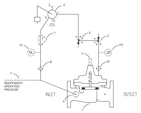
Schematic Diagram
Item Description
1. Hytrol (Main Valve)
2. CF1-C1 Float Control
Optional Features
Item Description
A. X46A Flow Clean Strainer
B. CK2 Isolation Valve
C. CV Flow Control (Closing)
F . Independent Operating Pressure
P. X141 Pressure Gauge
S. CV Speed Control (Opening)
V. X101 Valve Position Indicator
Y. X43 “Y” Strainer
Typical Applications
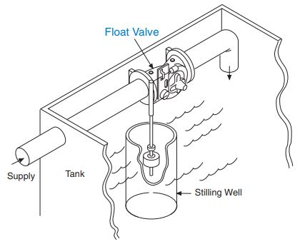
The Model 124-01/624-01 Float Valve is commonly mounted above the high water level in a tank. Globe pattern valves are supplied standard with the float control mounted on the cover as illustrated, with a
horizontal discharge. Angle valves are configured to discharge downward.
Note:
- We recommend protecting tubing and valve from freezing temperatures.
- Must be inspected periodically.
Installation
A stilling well (8″ minimum diameter) must be provided around the float. When the valve is mounted on top of the tank roof, a 2″ clearance hole should be provided for side movement of the float rod where the rod goes through the top of the tank.
A clear independent source of air or water may be used to operate the valve (option F). The pressure from this independent source must at all times be equal to or
greater than pressure at the valve inlet.
If minimum flowing line pressure is less than 10 psi, consult factory.
If the float control is remotely mounted from the main valve, the control may be installed at any elevation above the valve, provided the flowing line pressure in psi is greater than the vertical distance in feet between the valve and the float control. See the technical data sheet on Model CF1-C1 for additional information.
Model 124-01 (Uses 100-01 Hytrol Main Valve)
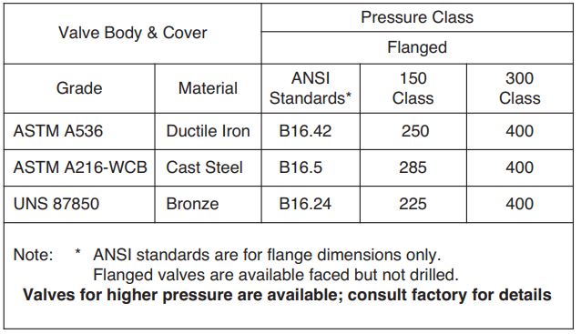
Pressure Ratings (Recommended Maximum Pressure – psi)
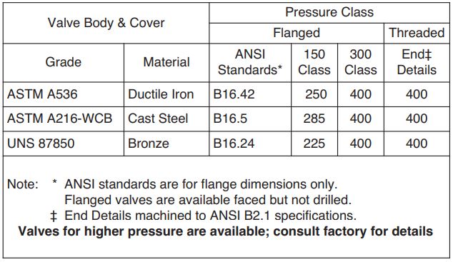
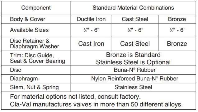
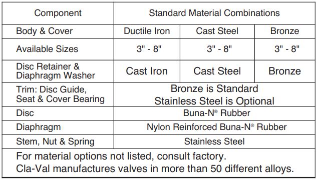
Materials
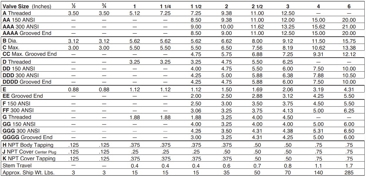
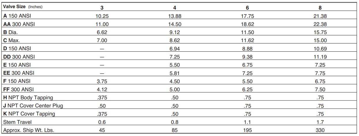
Dimensions (In inches)
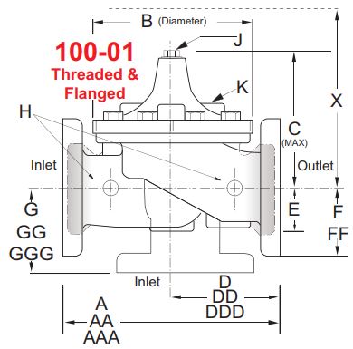
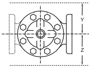
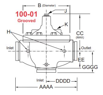
Model 124-01 Dimensions (inches)
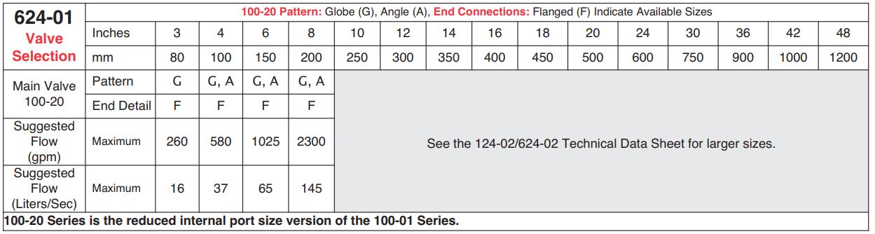
Model 624-01 (Uses 100-20 Hytrol Main Valve)
Pressure Ratings (Recommended Maximum Pressure – psi)
Materials
Dimensions (In inches)
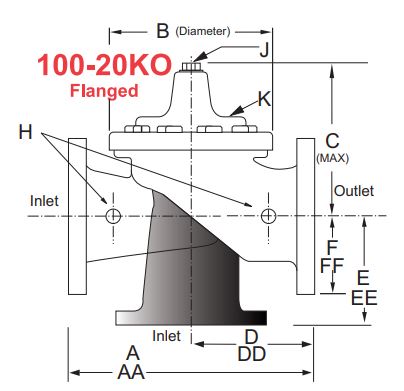
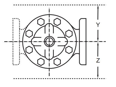
Model 624-01 Dimensions (inches)
Pilot System Dimensions
Pressure Rating
300 psi Max.
Temperature Rating
Water: to 180°F. Max.
Materials
In contact with operating fluid:
Nylon-reinforced Delrin,Stainless Steel,
Monel, with Buna-N® seals
Float linkage and float rod: Brass and PVC
Base plate: 316 Stainless Steel
Float: 304 Stainless Steel
Float
5 3/8″ diameter.
Float Rod
Standard: Two 12″ sections PVC rod, 6″ & smaller
12″ extension increments at additional cost.
Larger counterweight required if float
rod length exceeds 5′.
Optional: 24″ stainless steel rod, with
24″ extension increments at additional cost.
Larger counterweight required if float
rod length exceeds 2′.
If maximum temperature exceeds 160°F. specify
stainless steel float rod.
Adjustment Range
Level Differential:
1″ min. to 18″ max. with PVC rod.
1″ min to 40″ max. with stainless steel rod.
Operating Fluids
Clean liquids or gases compatible with
specified materials.
When Ordering, Please Specify
- Catalog No. 124-01 or No. 624-01
- Valve Size
- Pattern – Globe or Angle
- Pressure Class
- Threaded or Flanged
- Float Rod Material and Length
- Float Ball Material
- Desired Options
- When Vertically Installed