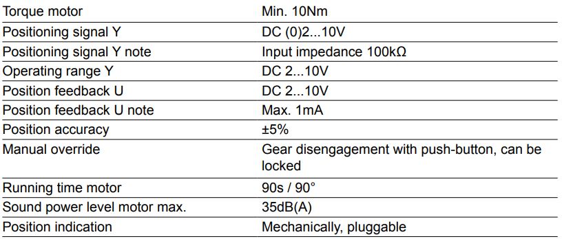
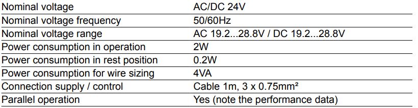
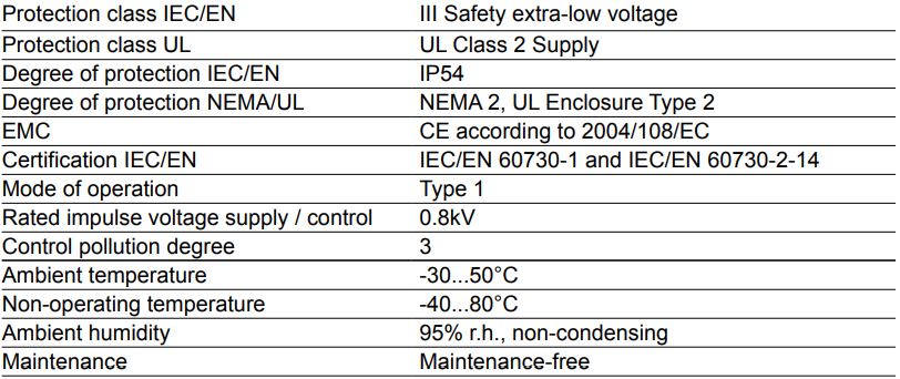
Technical data
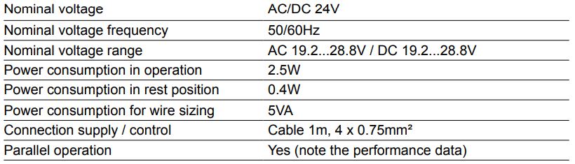
Electrical data
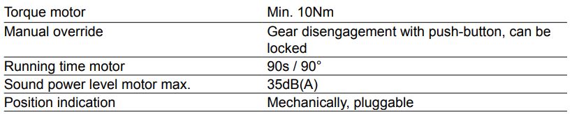
Functional data
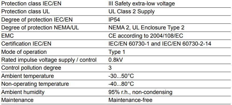
Safety
Weight
Safety notes
- This device has been designed for use in stationary heating, ventilation and air conditioning systems and is not allowed to be used outside the specified field of application, especially in aircraft or in any other airborne means of transport.
- Only authorised specialists may carry out installation. All applicable legal or institutional installation regulations must be complied during installation.
- The switch for changing the direction of rotation may only be operated by authorised specialists. The direction of rotation must not in particular be reversed in a frost protection circuit.
- The device may only be opened at the manufacturer‘s site. It does not contain any parts that can be replaced or repaired by the user.
- The cables must not be removed from the device.
- The device contains electrical and electronic components and is not allowed to be disposed of as household refuse. All locally valid regulations and requirements must be observed.
Product features
Mode of operation
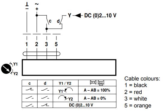
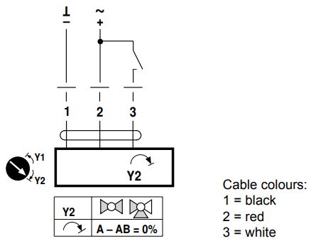
The actuator is connected with a standard modulating signal of DC (0)2…10V and travels to the position defined by the positioning signal. Measuring voltage U serves for the electrical display of the valve position 0…100% and as slave control signal for other actuators.
Simple direct mounting
Straightforward direct mounting on the ball valve with only one central screw. The assembly tool is integrated in the plug-in position indication. The mounting position in relation to the ball valve can be selected in 90° steps.
Manual override
Manual override with push-button possible (the gear is disengaged for as long as the button is pressed or remains locked).
High functional reliability
The actuator is overload protected, requires no limit switches and automatically stops when the end stop is reached.
Adjustable angle of rotation
Adjustable angle of rotation with mechanical end stops.
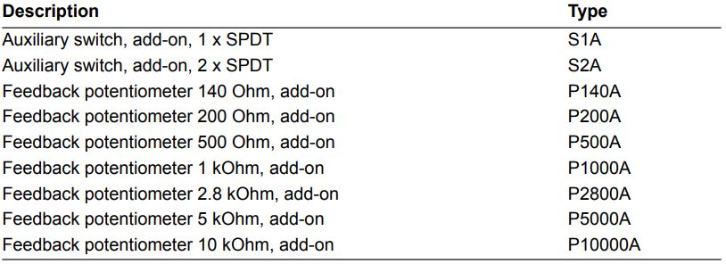
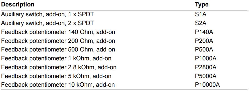
Accessories
Electrical accessories
Electrical installation
Notes
- Connection via safety isolating transformer.
- Parallel connection of other actuators possible. Observe the performance data.
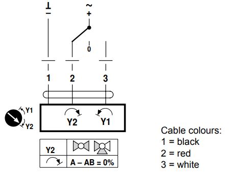
- Direction of rotation switch is covered. Factory setting: Direction of rotation Y2.
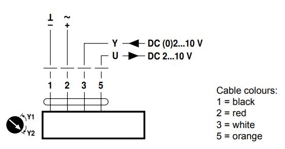
Wiring diagrams
AC/DC 24V, modulating
Override control (frost protection circuit)
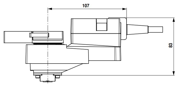
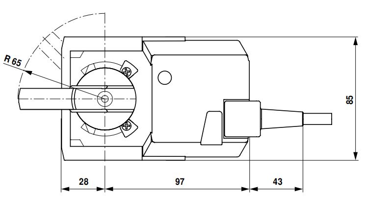
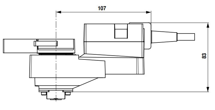
Dimensions [mm]
Dimensional drawings

Technical data
Electrical data
Functional data
Safety
Weight
Safety notes
- This device has been designed for use in stationary heating, ventilation and air conditioning systems and is not allowed to be used outside the specified field of application, especially in aircraft or in any other airborne means of transport.
- Only authorised specialists may carry out installation. All applicable legal or institutional installation regulations must be complied during installation.
- The switch for changing the direction of rotation may only be operated by authorised specialists. The direction of rotation must not in particular be reversed in a frost protection circuit.
- The device may only be opened at the manufacturer‘s site. It does not contain any parts that can be replaced or repaired by the user.
- The cables must not be removed from the device.
- The device contains electrical and electronic components and is not allowed to be disposed of as household refuse. All locally valid regulations and requirements must be observed
Product features
Simple direct mounting
Straightforward direct mounting on the ball valve with only one central screw. The assembly tool is integrated in the plug-in position indication. The mounting position in relation to the ball valve can be selected in 90° steps.
Manual override
Manual override with push-button possible (the gear is disengaged for as long as the button is pressed or remains locked).
High functional reliability
The actuator is overload-proof, requires no limit switches and automatically stops when the end stop is reached.
Adjustable angle of rotation
Adjustable angle of rotation with mechanical end stops.
Accessories
Electrical accessories
Electrical installation
Notes
- Connection via safety isolating transformer.
- Parallel connection of other actuators possible. Observe the performance data.
- Direction of rotation switch is covered. Factory setting: Direction of rotation Y2.
Wiring diagrams
AC/DC 24V, open-close
AC/DC 24V, 3-point
Dimensions [mm]
Dimensional drawings