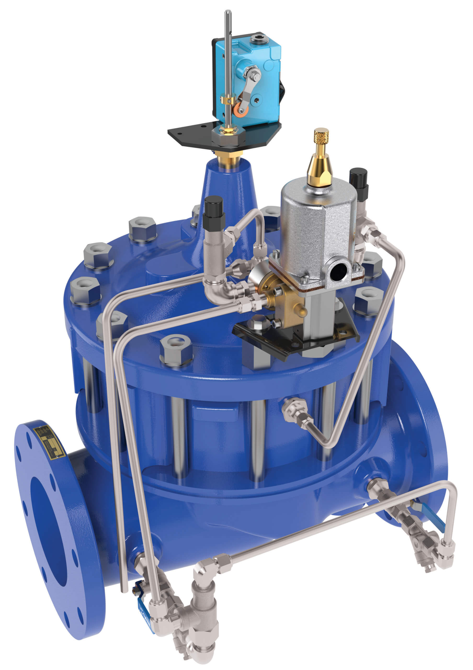
Booster Pump Control Valve
Product Advantages
- Built-in Check Valve
- Valve Uses Line Pressure for Operation
- Opening and Closing Rates Adjusted Separately
- Solenoid Control Can Be Operated Manually
- Can be integrated with SCADA when controlled by the PC-22D Electronic Pump Control Panel
The Cla-Val Model 60-11 Booster Pump Control Valve is a pilot operated valve designed for installation on the discharge of booster pumps to eliminate pipeline surges caused by the starting and stopping of the pump.
The pump starts against a closed valve. When the pump is started, the solenoid control is energized and the valve begins to open slowly, gradually increasing line pressure to full pumping head. When the pump is signaled to shut-off, the solenoid control is de energized and the valve begins to close slowly, gradually reducing flow while the pump continues to run. When the valve is closed, a limit switch assembly, which serves as an electrical interlock between the valve and the pump, releases the pump starter and the pump stops.
Should a power failure occur, a built-in lift-type check valve closes the moment flow stops, preventing reverse flow regardless of solenoid or diaphragm assembly position.
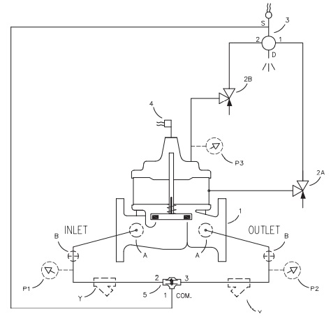
Schematic Diagram
Item Description
1. 100-03 Powercheck Main Valve
2. CV Flow Control
3. CSM11-A2-2 Solenoid Control
4. X105LCW Switch Assembly
5. CVS-1 Shuttle Valve
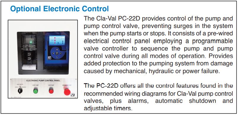
Optional Features
Item Description
A. X46A Flow Clean Strainer
B. CK2 Isolation Valve
P. X141 Pressure Gauge
Y. X43 “Y” Strainer
PC. PC-22D Pump Control Panel
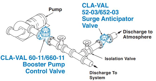
Typical Installation
Install the valve as shown to help prevent pipelines surges during pump starting and stopping. Flexible conduit should be used for electrical connections to the solenoid control and the limit switch.
A Cla-Val Model 52-03 Surge Anticipator Valve is recommended for power failure protection or the Model 652-03 if a reduced port valve is required.
Use the PC-22D Electronic Pump Control Panel for applications where electronic contol and integration with SCADA is desired.
Note: Installation with valve stem vertical up is recommended.
For horizontal stem installation use Cla-Val Model 60-73 or, if a reduced port valve is required, Model 660-73.
Pressure Ratings (Recommended Maximum Pressure - psi)
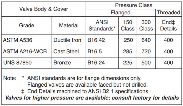
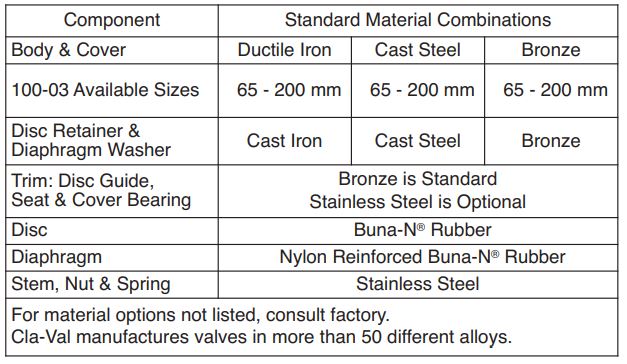
Materials
Model 60-11 (uses 100-03 Powercheck Main Valve)
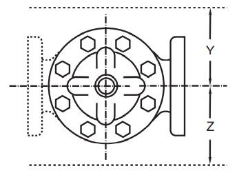
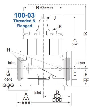
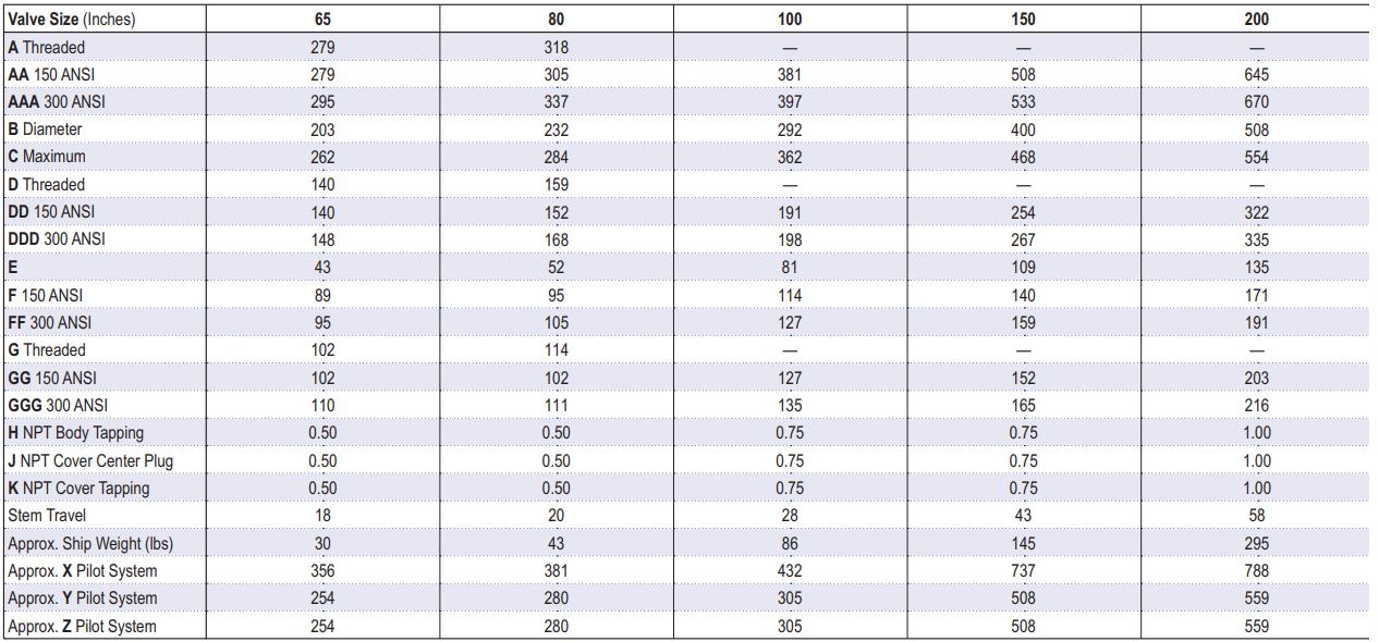
60-11 Series Metric Dimensions (In mm)
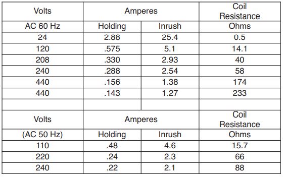
CSM11 Solenoid Control PowerConsumption
How to Order
When Ordering, Specify:
1. Catalog No. 60-11
2. Valve Size
3. Pattern – Globe or Angle
4. Pressure Class
5. Trim Material
6. Electrical Selection
7. Desired Options
8. When Vertically Installed
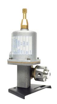
CSM11 Specifications
Enclosure General purpose NEMA Type 3; Aluminum
Note: For other enclosures and
NEMA Types, consult factory
Housing Body — Aluminum
Trim — Stainless Steel
Operating Pressure: Maximum pressure 300 psi,
for higher pressure consult factory.
Coil Insulation Class A (molded)
AC voltage 15.4 watts
Pilot System Specifications
Temperature Range
Water to 180°F Max
Materials
Standard Pilot System Materials
Pilot Control: Low Lead Bronze
Trim: Stainless Steel Type 303
Rubber: Buna-N® Synthetic Rubber
Optional Pilot System Materials
Pilot Systems are available with
optional Aluminum, Stainless Steel
or Monel materials.
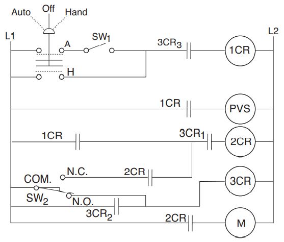
Wiring Diagram
Auto-Off-Hand = Selector Switch
1CR = Relay, DPST Normally Open
2CR = Relay, DPST Normally Open
3CR = Relay, TPST Normally Open
SW1 = Switch, Remote Start, Automatic
SW2 = Switch, SPDT, Valve Limit Switch Connect to N.C. Terminal
PVS = Pilot Valve Solenoid
M = Pump Motor Starter
Note: SW2 and PVS supplied by Cla-Val. All other electrical items supplied by customer. SW2 is included in the X105L switch assembly which is mounted on the pump control valve cover. Shown In Pump Off Position
Sequence Of Operation
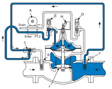
Pump Off…
With pump off, line pressure exists above the diaphragm holding the main valve closed.
Shuttle valve C always supplies highest pressure to solenoid control A through strainers B and F.
If power failure occurs when valve is open, the built-in check valve J closes immediately to prevent reverse flow.
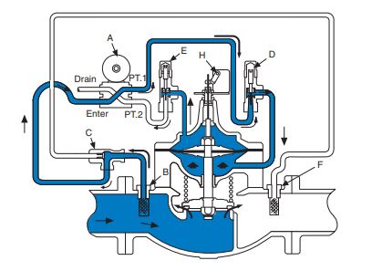
Starting Cycle…
Starting switch closes, pump starts, solenoid control energizes.
Upstream fluid flows to chamber below main valve diaphragm through strainer B, shuttle valve C, solenoid control A, and closing rate flow control D.
Valve opens slowly as fluid from diaphragm chamber is gradually released to atmosphere through opening rate flow control E and solenoid control A.
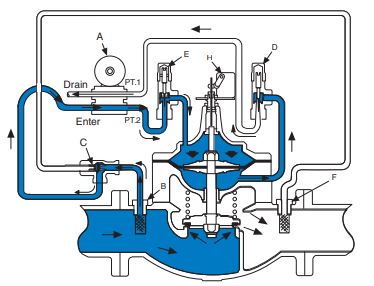
Stopping Cycle…
Starting switch opens, solenoid control de-energizes. Upstream fluid flows to valve diagram through strainer B, shuttle valve C, solenoid control A and opening rate Flow Control E.
Valve closes slowly as fluid below diaphragm chamber is gradually released to atmosphere through closing rate flow control D and solenoid control A.
Model 60-11 Flow Chart (Uses 100-03 Powercheck Main Valve)
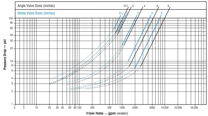
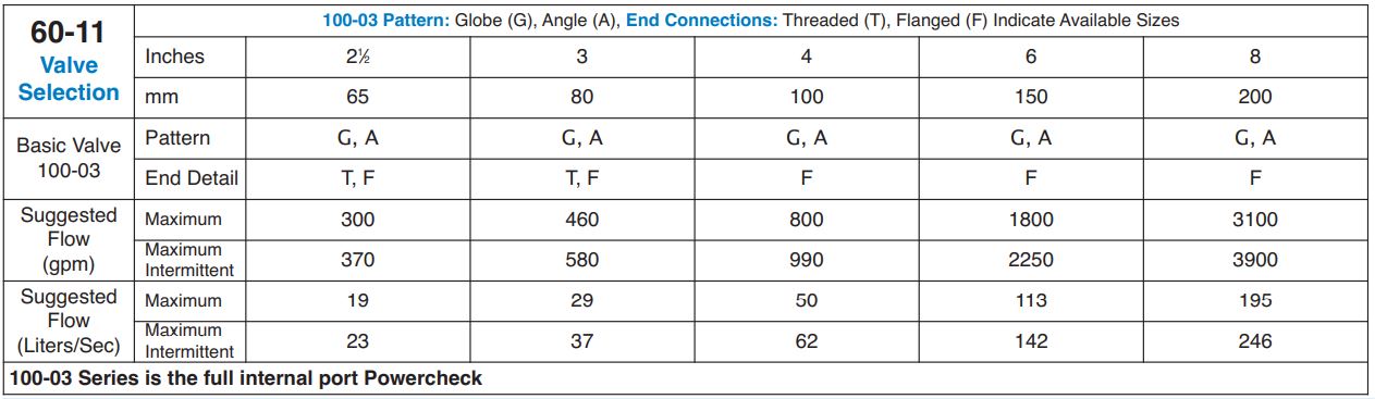
Valve Sizing
Sizing Model 60-11 Booster Pump Control Valves is similar to sizing non-modulating type valves. Simply select the smallest size valve that will handle the pump output at an acceptable head loss for the application.
Do not oversize. Oversizing a Booster Pump Control Valve will nullify its ability to prevent surges caused by the starting and/or stopping of the pump. Maximum flow values are given in the selection table above. Flow characteristics are shown on flow charts (over leaf) for these valve.
Example:
A booster pump with a rated output of 2650 liters/sec. and 4 psi is an acceptable head loss for the application. The flow chart for the 100-03 (60-11) indicates that a 200mm globe valve has less than 4 psi pressure drop at 2650 liters/sec.
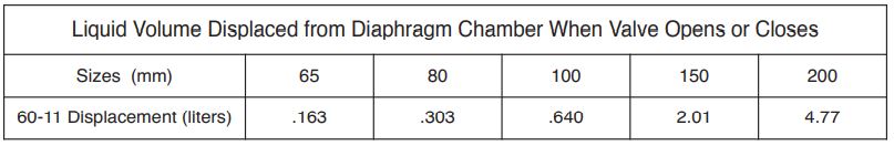
Drain Provisions
Each time the valve opens or closes, water is discharged from the solenoid exhaust port, the amount varying with the valve size. Provisions should be made for the disposal of this water. Exhaust tube mustbe free of any back pressure. Provide an air gap between the solenoid exhaust tube and drain facility
Note: Orifice plate assembly (X52E) may be attached to the main valve outlet flange, however, better control is obtained if it is located one to five pipe diameters downstream.
Orifice plate sensing connection should be located in the pipeline on the side of the orifice plate assembly. The orifice plate assembly should not be mounted directly to a butterfly valve. See E-X52E Data Sheet for Orifice Bore adjustment range.