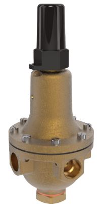
Combination Pressure Reducing & Pressure Sustaining Valve
Product Advantages
- Accurate Response to Slight Pressure Changes
- Check Feature Available
- Completely Automatic Operation
- Drip-Tight, Positive Seating Action
- Operation is Fully Hydraulic
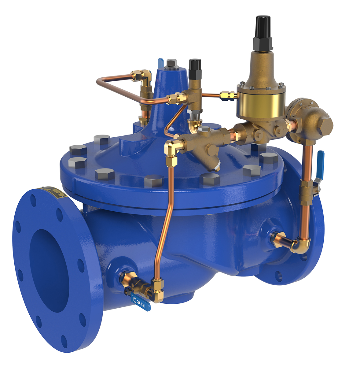
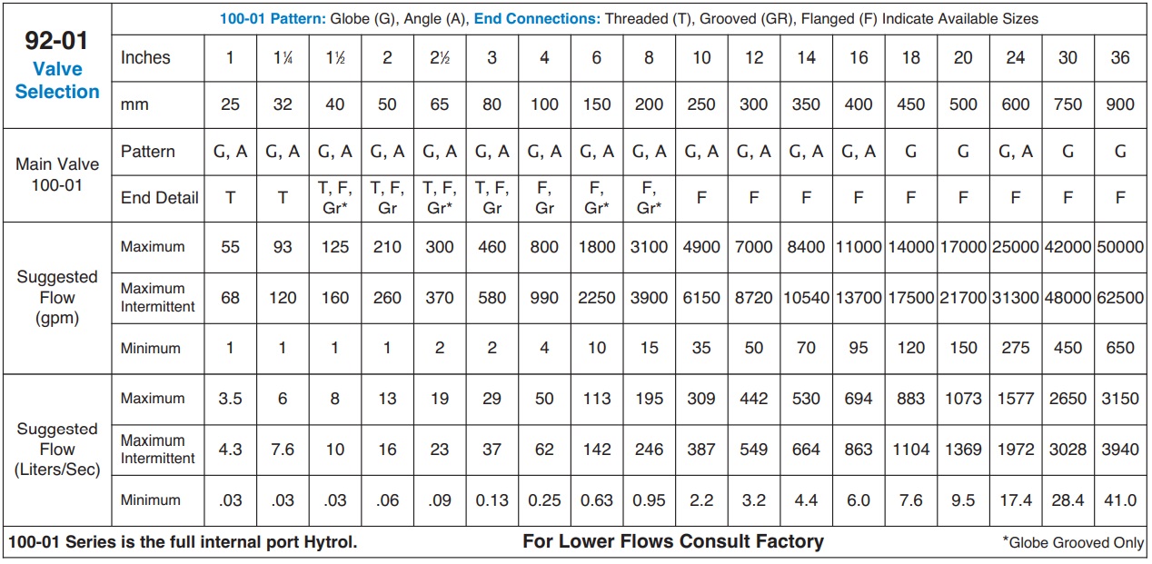
The Cla-Val Model 92-01 Combination Pressure Reducing and Pressure Sustaining Valve automatically performs two independent functions. It maintains a constant downstream pressure, regardless of fluctuating demand and sustains the upstream pressure to a predetermined minimum.
The pressure reducing control responds to slight variations in downstream pressure and immediately repositions the main valve to maintain the desired downstream pressure. The pressure sustaining control is normally held open by the upstream pressure, but modulates should the pressure drop to the control set point. This, in turn, modulates the main valve to sustain the desired upstream pressure.
If a check feature is added, and a pressure reversal occurs, the downstream pressure is admitted into the main valve cover chamber and the valve closes to prevent return flow.
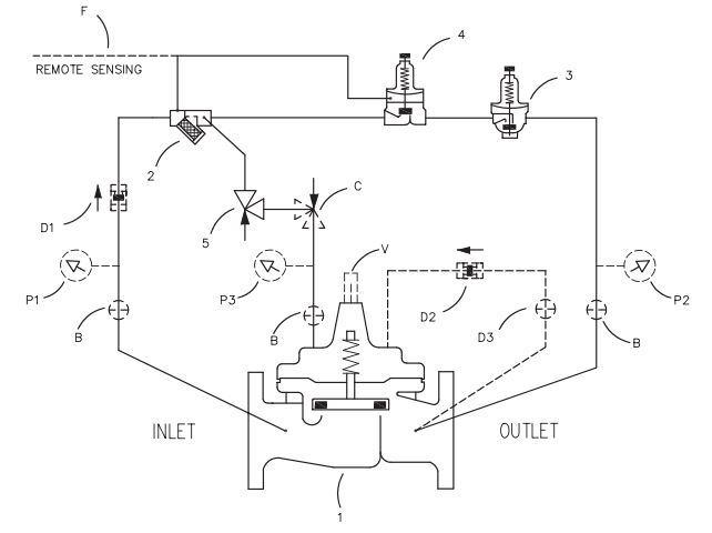
Schematic Diagram
Item Description
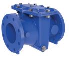
1. 100-01 Hytrol Main Valve
2. X44A Strainer & Orifice
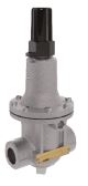
3. CRD Pressure Reducing Control
4. CRL-60 Pressure Relief Control
5. CV Flow Control (Opening)
Optional Features
Item Description
B. CK2 Isolation Valve
C. CV Flow Control (Closing)*
D. Check Valves With Isolation Valve
F. Remote Pilot Sensing
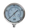
P. X141 Pressure Gauge
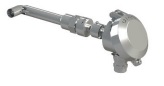
V. X101 Valve Position Indicator
* The (optional) closing speed control on this valve should
always be open at least three (3) turns off its seat.
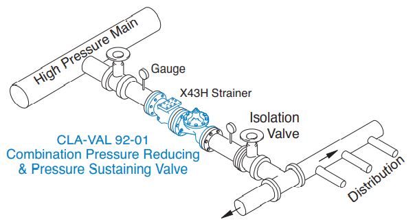
Typical Application
A Combination Pressure Reducing and Pressure Sustaining Valve is typically used to automatically reduce pressure for the downstream distribution network and sustain a minimum pressure in the high pressure main regardless of distribution demand.
Model 92-01 (Uses 100-01 Hytrol Main Valve)
Pressure Ratings (Recommended Maximum Pressure – psi)
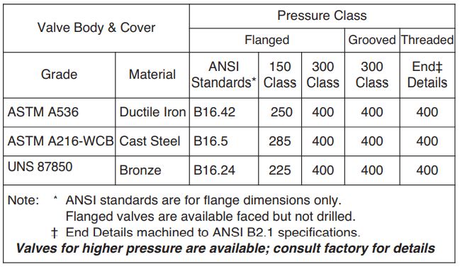
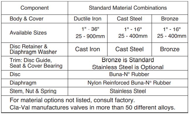
Materials
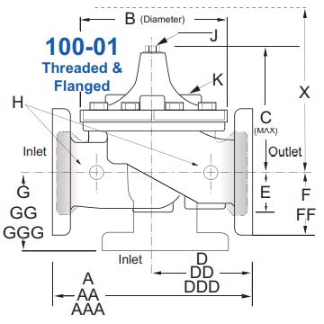
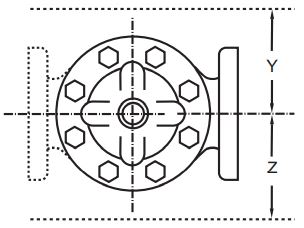
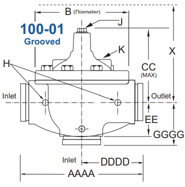
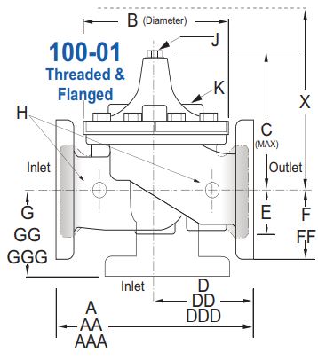
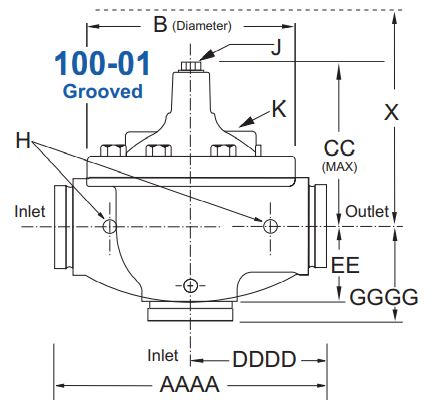
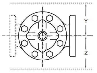
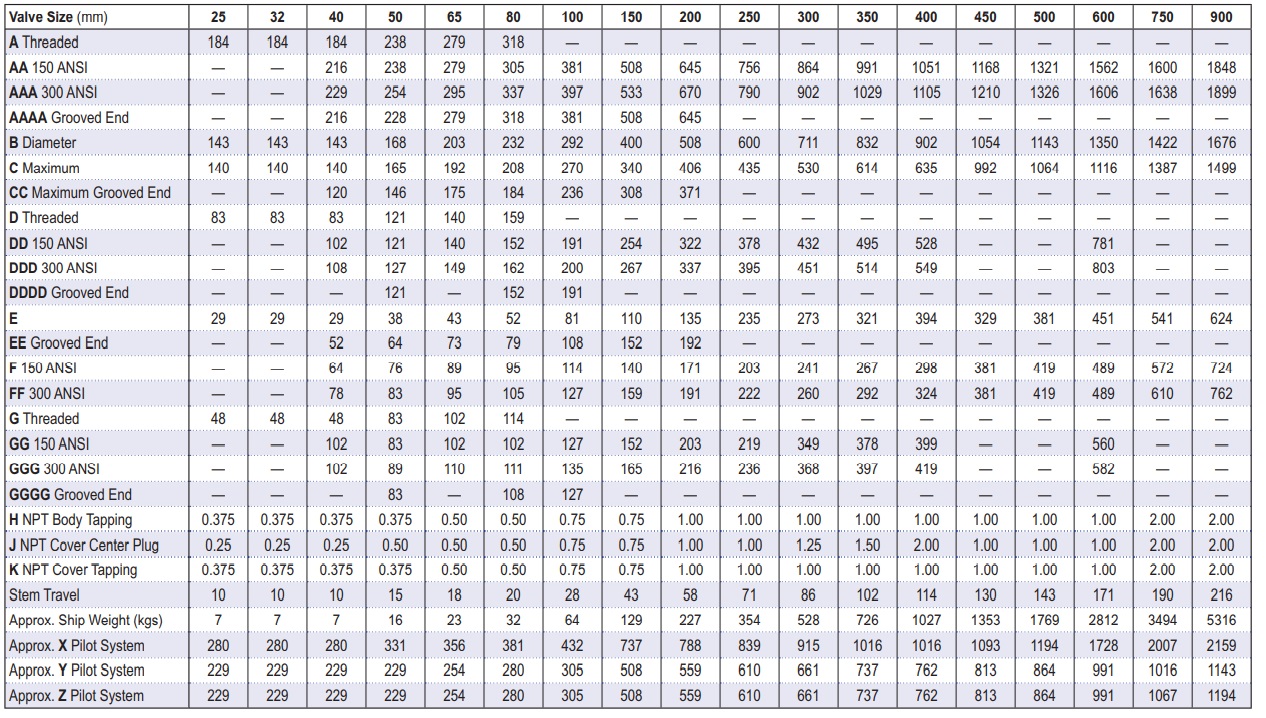
Model 92-01 Dimensions (In Inches)
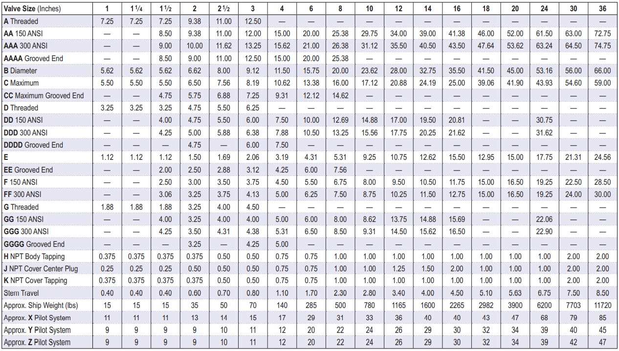
Model 92-01 Metric Dimensions (Uses the 100-01 Hytrol Main Valve)
Valve Options
X141 Pressure
Gauge
X101AR Valve
Position Indicator
with Air Release
X101
Valve Position
Indicator
X144 e-FlowMeter
X43H
Strainer
X43H
Strainer
Stainless
Steel Pilot
92-01 Dimensions (In mm)

CRD Pressure Reducing Pilot Control
The CRD Pilot is held open by the force of the compression spring above the diaphragm, and closes when the downstream pressure acting on the underside of the diaphragm exceeds the spring setting. The CRD senses downstream pressure directly.
Flow through the control responds to changes in downstream pressure. Turning the adjusting screw clockwise increases the delivery pressure. Turning it counterclockwise decreases the pressure. A resilient disc assures tight shut-off on dead-end service.
See the E-CRD E-Sheet for more details.
CRL-60 Pressure Relief Pilot Control
The Model CRL-60 is normally held closed by the force of the compression spring above the diaphragm. Control pressure is applied under the diaphragm. When the controlling pressure exceeds the spring setting, the disc is lifted off its seat, permitting flow through the control. When control pressure drops below the spring setting, the spring forces the control back to its normally closed position. The controlling pressure is applied to the chamber beneath the diaphragm through a sensing port on the CRL-60 body.
See the E-CRL-60 E-Sheet for more
details.
Pilot System Specifications
Adjustment Ranges
CRD
2 to 30 psi
15 to 75 psi
20 to 105 psi
30 to 300 psi*
CRL-60
0 to 75 psi
20 to 105 psi*
20 to 200 psi
100 to 300 psi
*Supplied unless otherwise specified
Other ranges available, please consult factory.
Materials
Standard Pilot System Materials
Pilot Control: Low Lead Bronze
Trim: Brass & Stainless Steel Type 303
Rubber: Buna-N® Synthetic Rubber
Optional Pilot System Materials
Pilot Systems are available with optional
Stainless Steel or Monel materials.
Note: Available with remote sensing control.
When Ordering,
Specify:
1. Catalog No. 92-01
2. Valve Size
3. Pattern – Globe or Angle
4. Pressure Class
5. Threaded or Flanged
6. Trim Material
7. Adjustment Range
8. Desired Options
9. When Vertically Installed