
Deep Well Pump Control Valve
Product Advantages
- Prevent Surges in Pipelines
- Simple Hydraulic Operation
- Adjustable Opening and Closing Speeds
- Solenoid Control Can Be Operated Manually
- Proven Reliable Design
The Cla-Val Model 61-02 Deep Well Pump Control Valve is designed to protect pipelines from surges caused by the starting and stopping of deep well pumps. This is a hydraulically operated diaphragm valve which is controlled by a solenoid pilot valve. Separate adjustable flow control valves in the pilot system regulate the opening and closing rates. A limit switch on the valve stem serves as an electrical interlockbetween the valve and the pump motor.
The operation of the valve is completely automatic and controlled by the solenoid valve. With the pump off, the valve is wide open. When the pump is started, the solenoid is energized and the valve begins to close slowly, discharging air and the initial rush of sand and water from the pump column to atmosphere. As the valve closes the pump output is gradually diverted into the main line, preventing the development of a starting surge.
When it is time to shut-off the pump, the solenoid is de energized. The pump continues to run while the pump control valve opens slowly, diverting pump output to atmosphere. As pump pressure gradually decreases, the main line check valve closes slowly, preventing shock or slam during the pump stopping cycle. When the pump control valve is wide open, the limit switch assembly releases the pump starter and the pump stops.
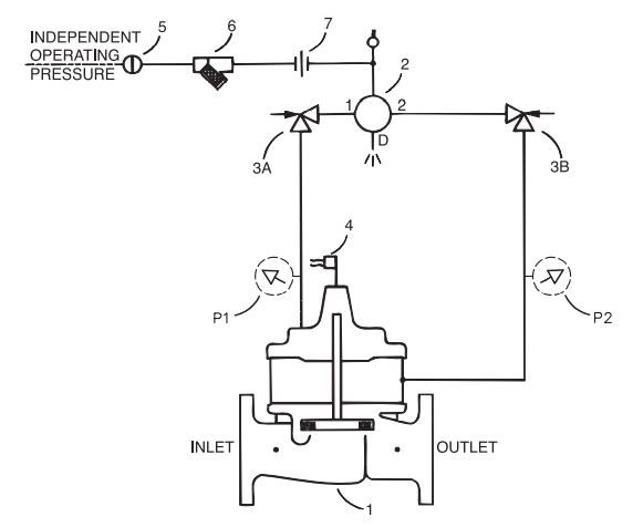
Schematic Diagram
Item Description
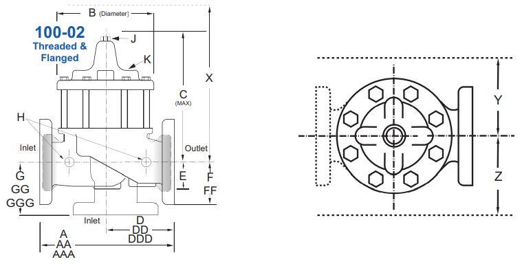
1. 100-02 Powertrol Main Valve
2. CSM11-A2-2 Solenoid Control
3. CV Flow Control
4. X105LOW Switch Assembly
5. CK2 Isolation Valve
6. X43 “Y” Strainer
7. Union
Options
Item Description
P. X141 Pressure Gauge
Typical Installation
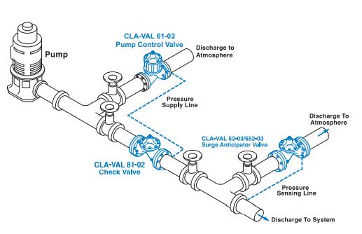
Install Model 61-02 valve as shown. Use a minimum of 12 mm tubing to connect operating pressure connection of the valve to the system side of check valve. Flexible conduit should be used for electrical connections to the solenoid control and the limit switch assembly. A Model 52-02 or 652-03 Surge Anticipator is recommended for power failure and surge protection.
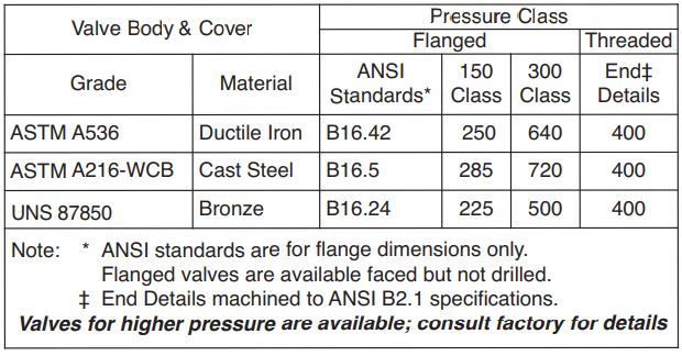
Pressure Ratings (Recommended Maximum Pressure - psi)
Materials
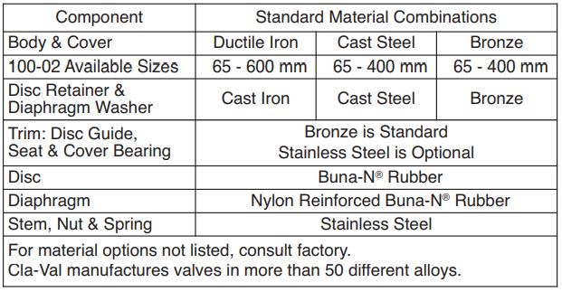
Model 61-02 (uses 100-02 Powertrol Main Valve)
Model 61-02 (uses 100-02 Powertrol Main Valve)
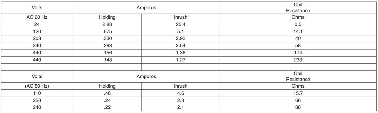
CSM11 Solenoid Control Power Consumption
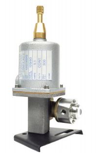
CSM11 Specifications
Enclosure General purpose NEMA Type 3; Aluminum
Note: For other enclosures and
NEMA Types, consult factory
Housing Body — Aluminum
Trim — Stainless Steel
Operating Pressure: Maximum pressure 300 psi,
for higher pressure consult factory.
Coil Insulation Class A (molded)
AC voltage 15.4 watts
Pilot System Specifications
Temperature Range
Water to 180°F Max
Materials
Standard Pilot System Materials
Pilot Control: Low Lead Bronze
Trim: Stainless Steel Type 303
Rubber:Buna-N® Synthetic Rubber
Optional Pilot System Materials
Pilot Systems are available with
optional Aluminum, Stainless Steel
or Monel materials.
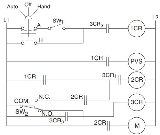
Wiring Diagram
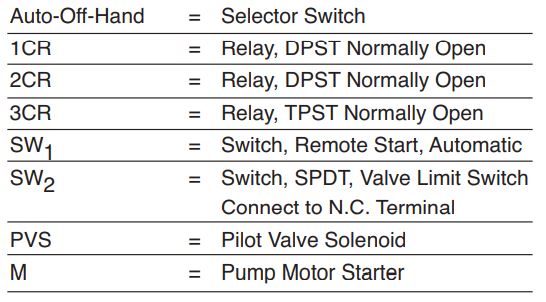
Note: SW2 and PVS supplied by Cla-Val. All other electrical items supplied by customer. SW2 is included in the X105L switch assembly which is mounted on the pump control valve cover.
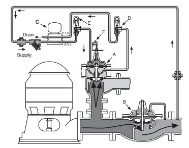
Shown In Pump Off Position
Sequence Of Operation
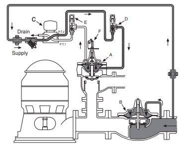
Pump Off...
With pump off, static line pressure holds the main line check valve “B” closed. Line pressure is transmitted through solenoid control “C” and speed control “D” to the lower chamber of valve “A”. Upper chamber of pump control valve “A” is vented to atmosphere so valve “A” is held wide open.
Starting Cycle...
Starting switch closes, pump starts, solenoid “C” energizes and shifts, allowing line pressure to flow into upper chamber of valve “A” through solenoid control “C” and opening speed control “E”. Closing speed of valve “A“ is controlled by speed control “D“ which limits the rate fluid is
relieved from under the diaphragm. As valve “A” closes, pumping pressure opens main line check valve “B”, gradually permitting full flow.
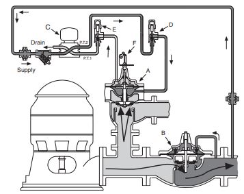
Stopping Cycle...
Starting switch opens, solenoid “C” de-energizes and shifts, as pump continues to run, pump pressure flows into lower chamber of valve “A” through solenoid “C” and opening speed control “D”. Pressure in upper chamber of valve “A” is relieved to atmosphere through opening speed control “E” and solenoid control “C”.As valve “A” opens, flow through main line check valve “B” gradually lessens until valve “A” is wide open and the limit switch “F” shuts off the pump.
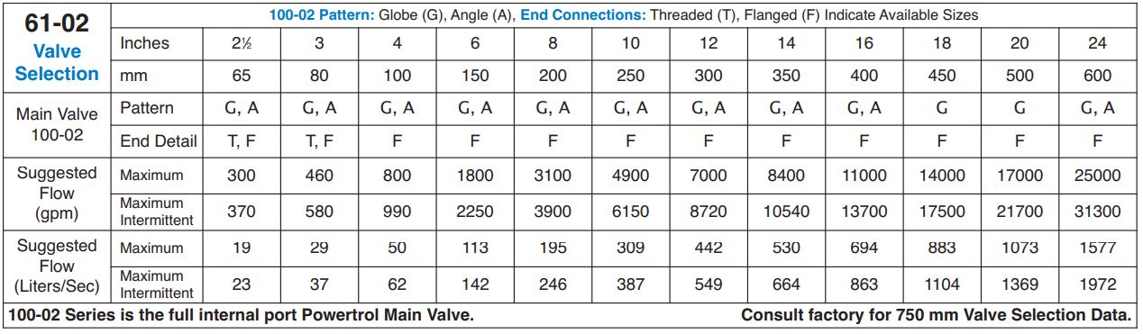
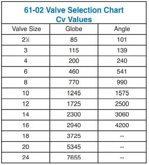
Selecting The Valve
To be effective, this valve must be sized so it relieves to atmosphere that part of the pump discharge head which is in excess of the normal system static pressure. To do this, the valve is sized to permit the full pump discharge through the valve at a pressure low enough to keep the system check valve from opening. As the pump control valve closes, the pumping pressure exceeds the system pressure and gradually flows into the system.
We recommend selecting a valve size which will have a pressure loss that is at least 10 psi less than the system static pressure. Use the flow rate which is found on the pump’s flow vs discharge pressure chart. Select the flow corresponding to the system static pressure, less 10 psi.
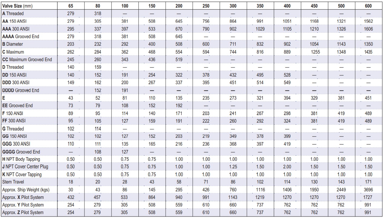
Determining Valve Size
- Determine the system’s static pressure (the pressure downstream of the check valve with the pump off); subtract 10 psi, this is the Design Pressure P.
- From the pump’s flow vs. discharge pressure curve, determine the flow (Q) at the Design Pressure P.
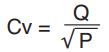
- Using the formula, calculate the Cv
- Select the valve size from the table which has a Cv that is equal to, or greater than, the calculated Cv in step 3 above.
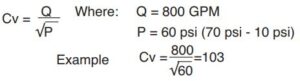
Example
- System Static Pressure with the pump off = 70 psi.
- Determine the Design Pressure P by subtracting 10 psi (70 psi – 10 psi = 60 psi Design Pressure)
- From the pump curve we determine that the valve must allow a flow of 800 GPM at 60 psi.
- Using the Formula:
Example (continued)
5. From the table above the best valve choice is: 80 mm 61-02 Globe Pattern
Drain Provisions
Each time the valve opens or closes, water is discharged from the solenoid exhaust port, the amount varying with the valve size. Provisions should be made for the disposal of this water. Exhaust tube must be free of any back pressure. Provide an air gap between the solenoid exhaust tube and drain facility.
When Ordering, Specify:
1. Catalog No. 61-02
2. Valve Size
3. Pattern – Globe or Angle
4. Pressure Class
5. Trim Material
6. Electrical Selection
7. Desired Options 8. When Vertically Installed