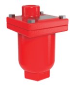
Fire Air Release Valve
Series 580
Product Advantages
- Ductile Iron Body
- Stainless Steel Trim and Float
- Easily serviced without removal from pipeline
- Working pressures to 175 and 300
- Engineered for drip tight seal at low pressures
Cla-Val Series 34 Fire Protection System Air Release Valves are designed to vent entrained air that collects at high points in a pipeline. This valve continuously eliminates air from a system by releasing small quantities of air before large air pockets can occur. In many installations, continuing accumulations of air in the pipeline (lacking air release valves); cause flow capacity to slowly decrease; power consumption slowly increases; un-noticeable at first, until flow drops dramatically, even stopping due to air blocks in the piping. Another problem resulting from excessive air accumulation is unexplained pipeline rupture. These ruptures are passed off as the result of ground settling or defective pipe, Where as in reality its large air pockets that greatly increase pressure surges (normally occurring) when flow stops and starts causing the rupture. During normal pipeline operation, air accumulation at the high point will displace the liquid within the air valve and lower the water level in relation to the float. As level of the liquid lowers, where the float is no longer buoyant, the float drops and opens the valve orifice seat and permitting accumulated air to be exhausted to atmosphere. After air is released, the liquid level in the air valve rises and closes the valve orifice seat. This cycle automatically repeats as air accumulates inside the air release valve, thereby preventing the formation of air pockets.
Installation
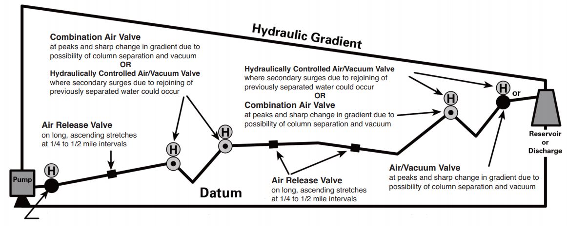
Series 34 Fire Protection System Air Release Valves are typically installed at high-points in pipelines and at regular intervals, of approximate 1/2 mile, along uniform grade line pipe.
Mount the unit in the vertical position on top of the pipeline with an isolation valve installed below each valve in the event servicing is required. A vault with adequate air venting and drainage is recommended.
Note:
Vacuum check valves can be supplied on the discharge of all size airrelease valves to prevent airre-entering the system; during negative pressure conditions
Purchase Specifications
The fire protection system air release valve shall be of the float operated, simple lever or compound lever design, and capable of automatically releasing accumulated air from a fluid system while the system is pressurized and operating.
An adjustable designed orifice button shall be used to seal the valve discharge port with drip-tight shut-off. The orifice diameter must be sized for use within a given operating pressure range to insure maximum air venting capacity.
The float shall be of all stainless steel construction and
guaranteed to withstand the designed system surge pressure without failure. The body and the cover shall be ductile iron and valve internal parts shall be stainless steel and VitonTM or Buna-N® (standard)for water tight shut-off.
The air release valve shall be manufactured per ANSI/AWWA C512-04 Series 34 from Cla-Val in Newport Beach, CA, USA.
Liquid level control can be provided by using a float switch or electrode probe which sends an electrical signal to open or close the valve as needed.
Sizes
1/2″, 3/4″, 1″, 2″, 3″ NPT
Pressure Ratings (see note)
175 UL/FM
300 UL/FM
Temperature Range
Water to 180°F
Note: Specify when operating
pressure below 10 PSI
Materials
Body and Cover:
Ductile Iron ASTM 536 65-45-12
Float:
Stainless Steel
Internal Parts:
Stainless Steel
Seal:
VitonTM or Buna-N® (Standard)
Air Release Valve Sizing
Air release valve sizing requires determining the volume of air that must be released from pipeline high points during normal operation and the diameter of the pipeline. Series 34 Fire Protection System Air Release Valves are primarily used to continuously release pockets of air (as they develop) from high point, hence it is not critical to determine exact volume of air to be released.
Air Release Valve Sizing Chart For Water Pipelines

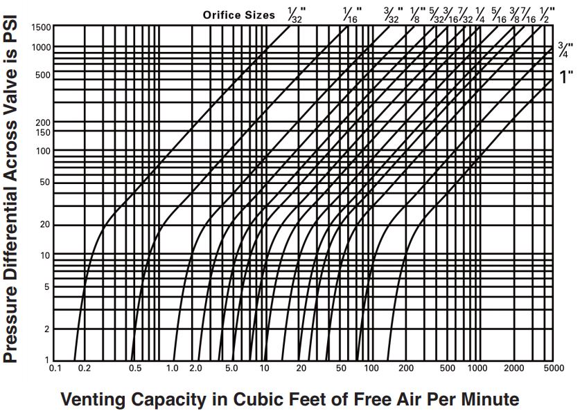
Venting Capacity Graph for Air Release Valves
Valve Selection Based on Venting Capacity
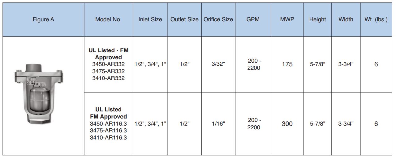
Air Release Valve Sizing Chart For Water Pipelines
Follow these steps to select and size an air release valves when a specific venting capacity is required:
Enter graph with required system pressure and venting capacity Read off nearest orifice diameter to intersection of pressure and capacity lines on graph Enter table above with orifice diameter and select valve that can use this orifice diameter with the corresponding pressure

Series 34 Fire Protection System Air Release Valve Technical Data

Installation Tips
- The effectiveness of Series 34 Air Release Valve is dependent upon it being located at appropriate high points in a pipeline and at uniform intervals of approximately 2500 feet on horizontal pipelines.
- There are four variables that can cause an air pocket to form slightly downstream of the true high point in a piping system:
1. Severity of the slope adjacent to the high point or change of gradient
2. Velocity of the liquid
3. Texture of the inside surface of the pipe being used
4. Viscosity of the fluid It is recommended where an air pocket can form slightly downstream of the high point, to install additional Series 34 Air Release Valve at this point. - Cla-Val has available, upon request, a Slide Rule Air Valve Calculator. It will greatly reduce the amount of time to size valves for pipeline service
Other typical applications include:
1. Centrifugal pumps
2. Hydropneumatic tanks
3. Enclosed systems
4. Sewage lines
When Ordering, Please Specify:
1. Model Number
2. Inlet Size (NPT)
3. Inlet Pressure Rating
4. Orifice Size