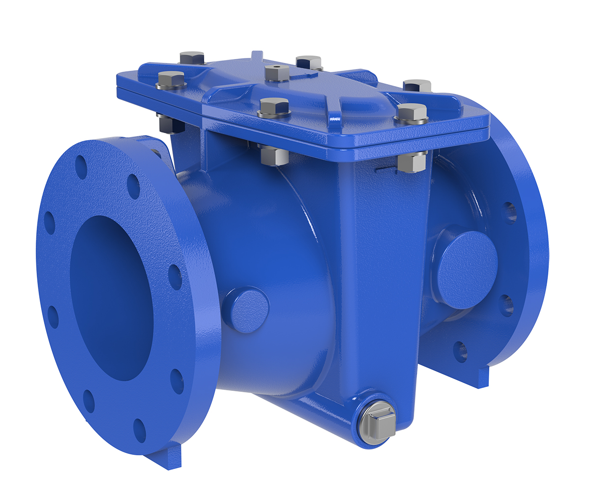
X43H H Style Strainer
Product Advantages
- Low Pressure Drop
- Ductile Iron with NSF/ANSI 61 Fusion Bonded Epoxy Coating Construction with a 316 Stainless Steel Strainer
- Large Flow Area H-Style Design
- Service Without Removal From Line
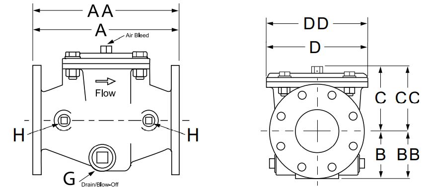
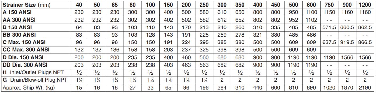
Dimensions
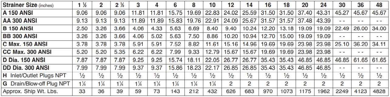
Specifications
Sizes (Inches): 11⁄2, 2, 21⁄2, 3, 4, 6, 8, 10, 12, 14, 16, 18, 20, 24, 30, 36 and 48
Sizes (mm): 40, 50, 65, 80,100, 150, 200, 250, 300, 350, 400, 450, 500, 600, 750, 900, 1200
Ends: Flanged, ANSI Class 150 and 300 (Note: 300# Flanges are Raised Face)
Max Pressure Rating: 150# – 250 psi • 300# – 400 psi
Temperature: Maximum 175°F
Materials:
Body & Cover: Ductile Iron ANSI B16.42; Fusion Bonded Epoxy Coating Standard
Cover Seal: Buna-N® Synthetic Rubber
Strainer: 316 Stainless Steel; Ductile Iron, Epoxy Coated Frame
Strainer Mesh Sizes: Standard 10 mesh / 2000 Micron / Openings 0.078 inch • Optional .039 and .059 inch openings available
Drain/Blow-Off: Connection furnished with Standard Stainless Steel Plug
Cover Fasteners: Stainless Steel
Model X43H Flow Chart
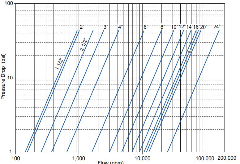
CV Factor

Cv in gpm = gpm @ 1psid head loss • Cv in l/s = l/s @ 1bar head loss
*Consult factory to confirm flow data for 30-inch/750mm and larger strainers
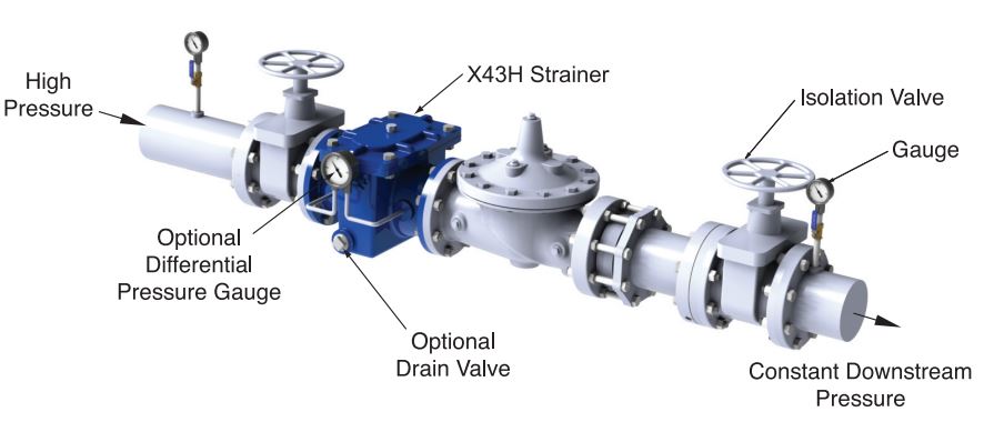
Model X43H Strainer Typical Application
Strainer Options
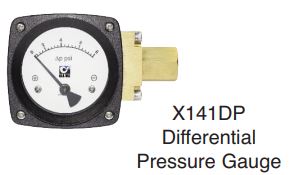
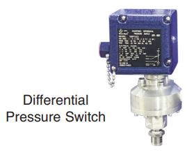
Product Details
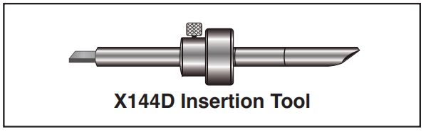
Insertion Tool and Locking Ring
- Required for installation
- Tool allows the proper installation and alignment
of the bluff body to be parallel to upstream flow
Power Requirement
- 12/24 VDC, 1.0 Watts minimum
X144D e-Flow Meter Sizing
- The X144D threads directly into the inlet tapping of a Cla-Val Control Valve. The size of the e-FlowMeter is dependent on the specific valve size for which it has been calibrated – no additional fittings are required. See dimension chart on previous page.
Cabling
- The unit is supplied with 30 feet of shielded cable.
Maximum Operating Pressure : 400 PSI
X144D e-FlowMeter Operational Flow Range = from 0.5 ft/s to 20 ft/s
X144D e-FlowMeter Analog Range (4-20mA Scaling): Factory Settings
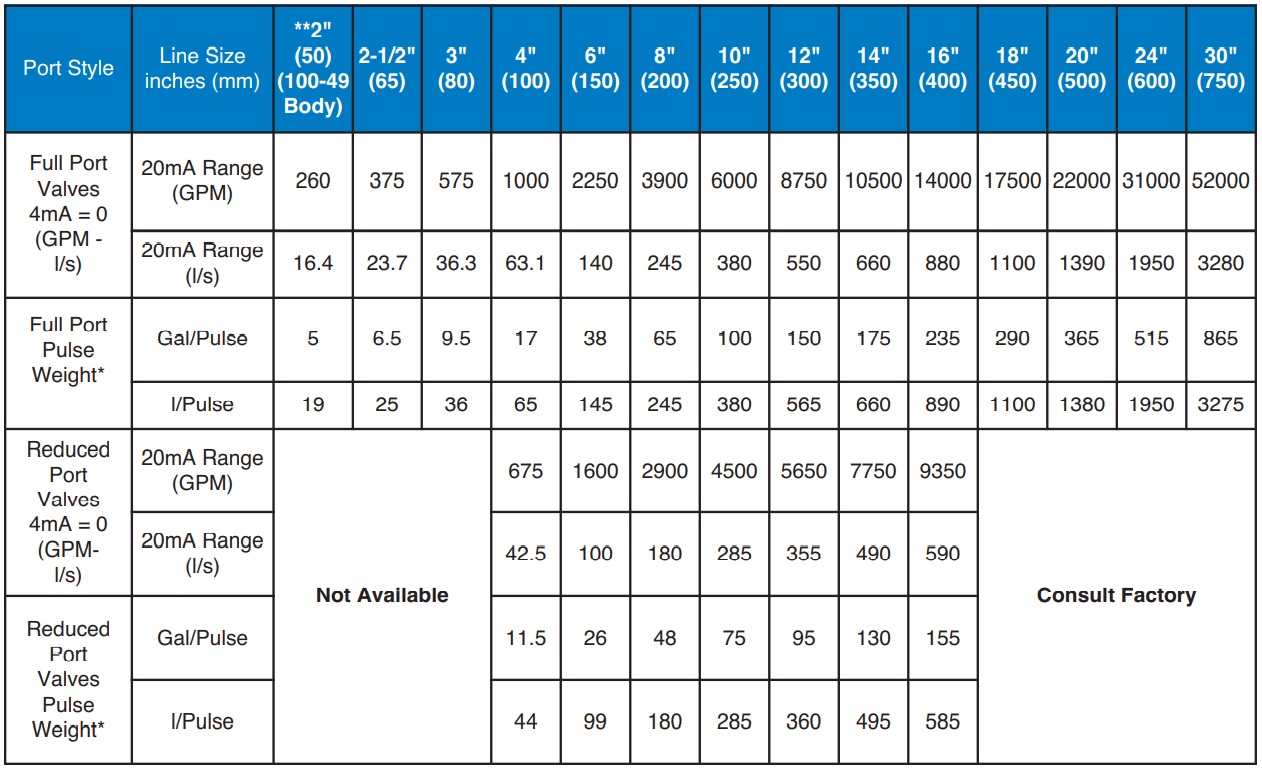
* Pulse Width = 250ms **2″ X144D e-FlowMeter may be installed on new valves only