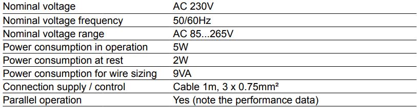
Technical data
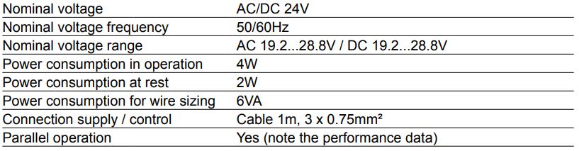
Electrical data
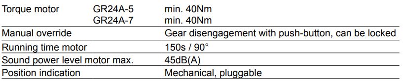
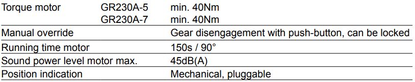
Functional data
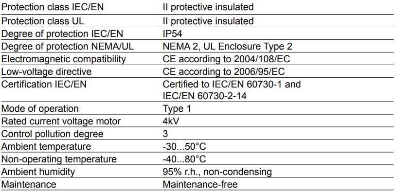
Safety
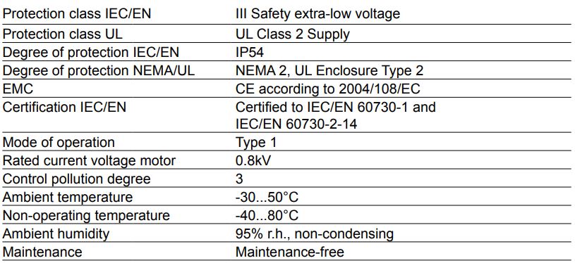
Mechanical data

Weight
Safety notes
- This device has been designed for use in stationary heating, ventilation and air conditioning systems and is not allowed to be used outside the specified field of application, especially in aircraft or in any other airborne means of transport.
- Only authorised specialists may carry out installation. All applicable legal or institutional installation regulations must be complied during installation.
- The switch for changing the direction of rotation may only be operated by authorised specialists. The direction of rotation must not in particular be reversed in a frost protection circuit.
- The device may only be opened at the manufacturer‘s site. It does not contain any parts that can be replaced or repaired by the user.
- The cables must not be removed from the device.
- The device contains electrical and electronic components and is not allowed to be disposed of as household refuse. All locally valid regulations and requirements must be observed.
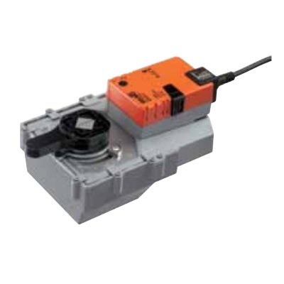
Product features
Simple direct mounting
Simple direct mounting on the rotary valve with mounting flange. The mounting position in relation to the fitting can be selected in 90° steps.
Manual override
Manual override with push-button possible (the gear is disengaged for as long as the button is pressed or remains locked).
High functional reliability
The actuator is overload-proof, requires no limit switches and automatically stops when the end stop is reached.
Combination valve/actuator
For valves with the following mechanical specifications in accordance with ISO 5211 F05:
– Square stem head SW = 14mm for form-fit coupling of the rotary actuator.
– Hole circle d = 50mm
For valves with the following mechanical specifications in accordance with ISO 5211 F07:
– Square stem head SW = 17mm for form-fit coupling of the rotary actuator.
– Hole circle d = 70mm
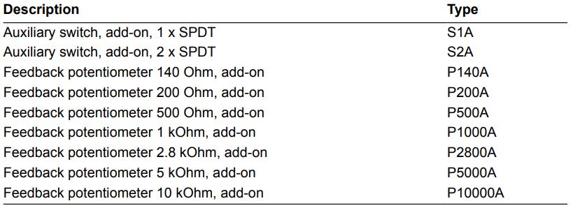
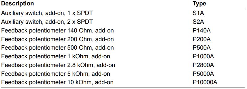
Accessories
Electrical accessories
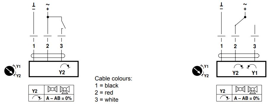
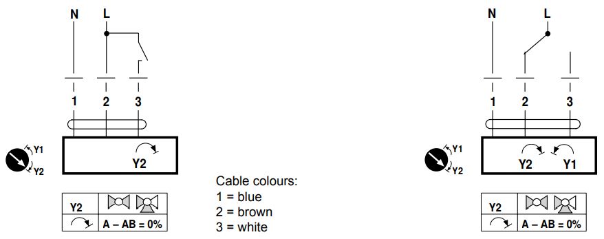
Wiring diagram
Notes
- Connection via safety isolating transformer.
- Parallel connection of other actuators possible. Observe the performance data.
- Direction of rotation switch is covered. Factory setting: Direction of rotation Y2.
GR24A-7
AC/DC 24V, open-close
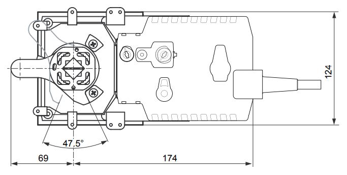
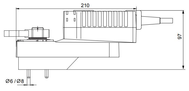
Dimensions [mm]
GR24A-5/-7
Wiring diagram
Notes
- Connection via safety isolating transformer.
- Parallel connection of other actuators possible. Observe the performance data.
- Direction of rotation switch is covered. Factory setting: Direction of rotation Y2.
GR24A-5
AC/DC 24V, open-close
Technical data
Electrical data
Functional data
Safety
Mechanical data

Weight
Product features
Manual override
Manual override with push-button possible (the gear is disengaged for as long as the button is pressed or remains locked).
High functional reliability
The actuator is overload-proof, requires no limit switches and automatically stops when the end stop is reached.
Simple direct mounting
Simple direct mounting on the rotary valve with mounting flange. The mounting position in relation to the fitting can be selected in 90° steps.
Combination valve/actuator
For valves with the following mechanical specifications in accordance with ISO 5211 F05:
– Square stem head SW = 14mm for form-fit coupling of the rotary actuator.
– Hole circle d = 50mm
For valves with the following mechanical specifications in accordance with ISO 5211 F07:
– Square stem head SW = 17mm for form-fit coupling of the rotary actuator.
– Hole circle d = 70mm
Accessories
Electrical accessories
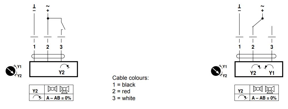
Wiring diagram
Notes • Caution: Power supply voltage!
- Parallel connection of other actuators possible. Observe the performance data.
- Direction of rotation switch is covered. Factory setting: Direction of rotation Y2
GR230A-5
AC/DC 230V, open-close
Dimensions [mm]
GR230A-5
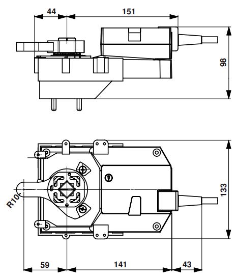
GR230A-7