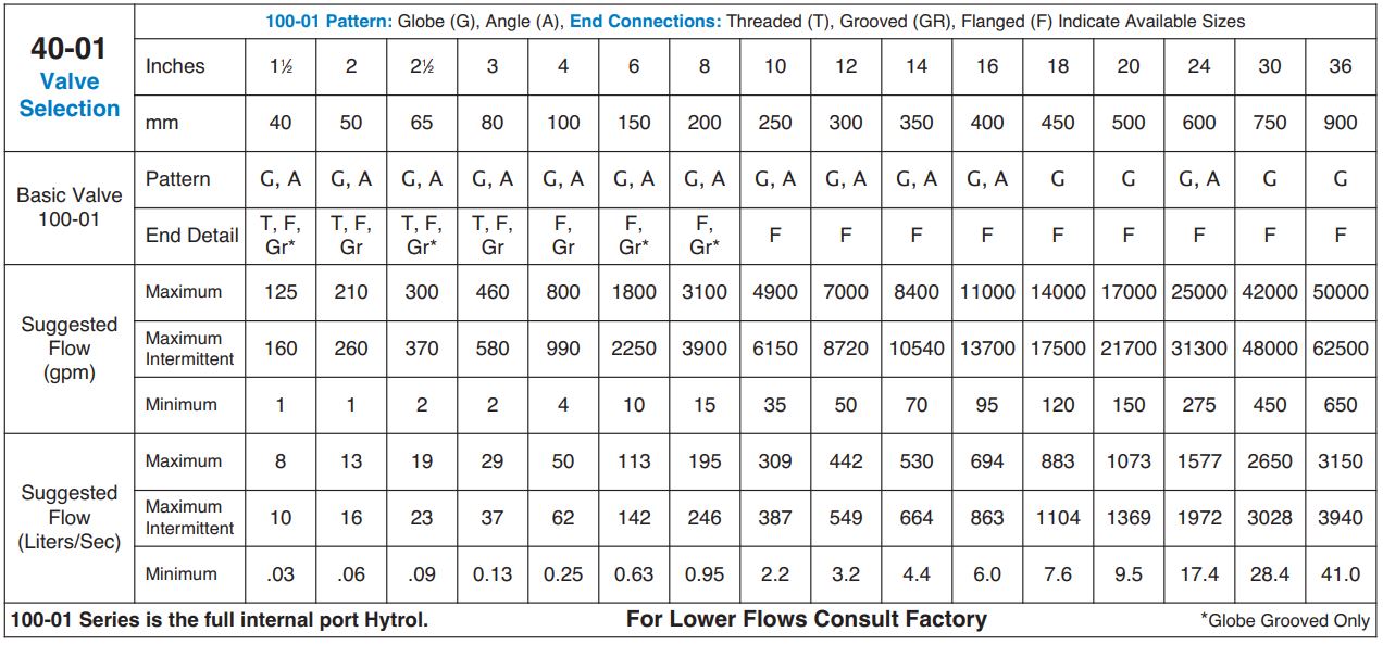
Rate of Flow Control Valve
Series 580
Product Advantages
- Accurately Limits Flow Rate
- Completely Automatic Operation
- Includes Orifice Plate with Holder
- Optional Check Feature
- Easily Adjusted
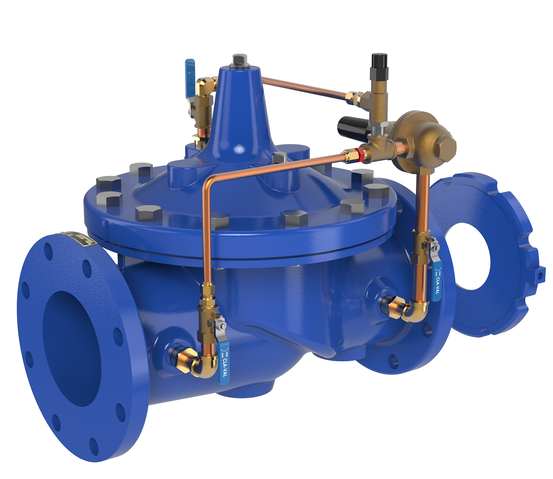
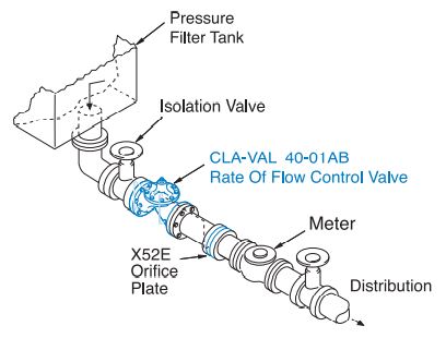
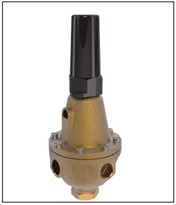
The Cla-Val Model 40-01 Rate of Flow Control Valve prevents excessive flow by limiting flow to a preselected maximum rate, regardless of changing line pressure. It is a hydraulically operated, pilot controlled, diaphragm valve. The pilot control responds to the differential pressure produced across an orifice plate installed downstream of the valve. Accurate control is assured as very small changes in the controlling differential pressure produce immediate corrective action of the main valve. Flow rate adjustments are made by turning an adjusting screw on the pilot control.
The Model 40-01 includes an orifice plate with a holder that should be installed one to five pipe diameters downstream of the valve. If the check feature option is added and a pressure reversal occurs, the downstream pressure is admitted into the main valve cover chamber
and the valve closes to prevent return flow. See X52E data sheet for sizing selection.
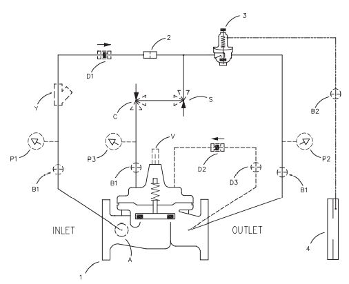
Schematic Diagram
Item Description
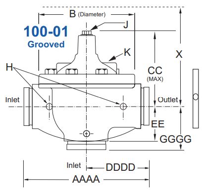
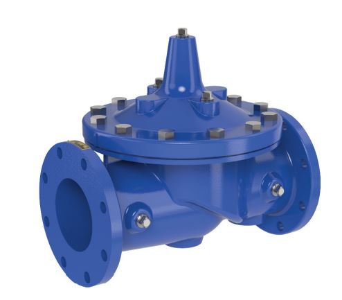
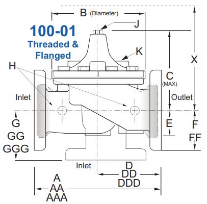
1. 100-01 Hytrol Main Valve
2. X58C Restricting Fitting
3. CDHS18 Differential Control
4. X52E Orifice Plate Assembly
Optional Features
Item Description
A. X46A Flow Clean Strainer
B. CK2 Isolation Valve
C. CV Flow Control (Closing)
D. Check Valves with Isolation Valve
P. X141 Pressure Gauge
S. CV Speed Control (Opening)
V. X101 Valve Position Indicator
Y. X43 “Y” Strainer
Typical Applications
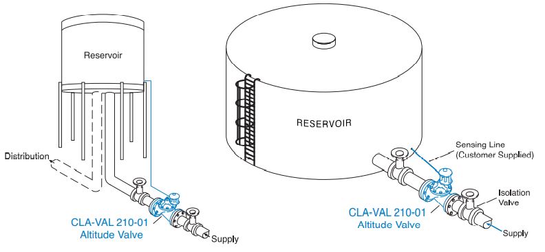
Used on reservoirs where the water is withdrawn through a separate line or through a bypass equipped with a check valve. The valve opens to refill the reservoir when the water lowers below the shut-off level. For more information see page 4 or data sheet E-CDS6A.
*Note: The reservoir pressure sensing line should be 3⁄4″ minimum I.D. installed with a 2° slope from the valve to the reservoir to avoid air pockets. Altitude Valve For One-Way Flow
Note: We recommend protecting tubing and valve from freezing temperatures.
Typical Applications
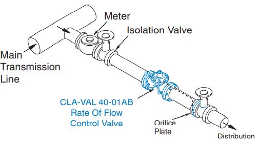
The 40-01 is typically installed where water supply to a system must be limited to a preset maximum flow rate. The valve is easily set to maintain the maximum allowable flow rate.
The 40-01 is typically installed as a pressure type filter effluent control valve where a constant flow rate is maintained as head loss through the filter varies.
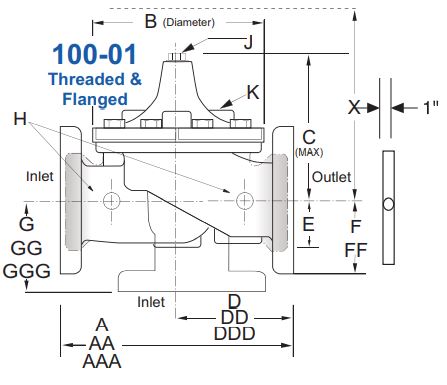
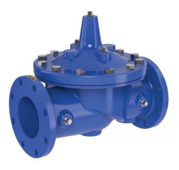
Model 40-01 (Uses 100-01 Hytrol Main Valve)
Pressure Ratings (Recommended Maximum Pressure – psi)
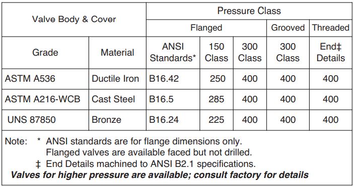
Materials
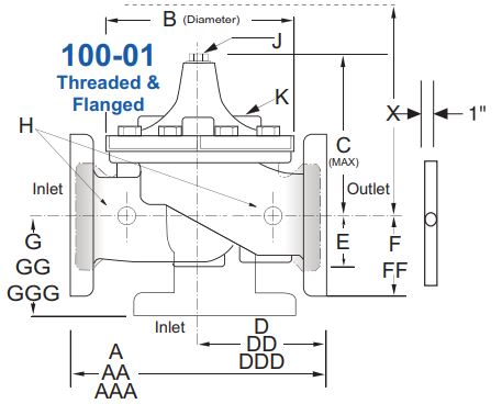
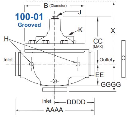
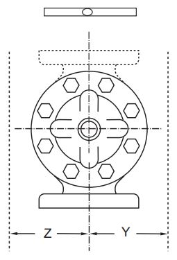
Model 40-01 Dimensions (In Inches)
Pressure Ratings (Recommended Maximum Pressure – psi)
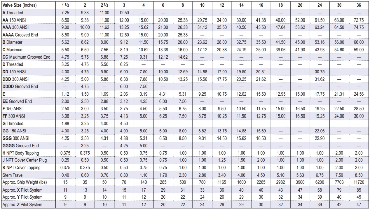
Model 40-01 Metric Dimensions (Uses 100-01 Main Valve)
Model 210-01 Metric Dimensions (Uses Main Valve Model 100-01)
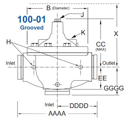
Model 40-01 Dimensions (In mm)
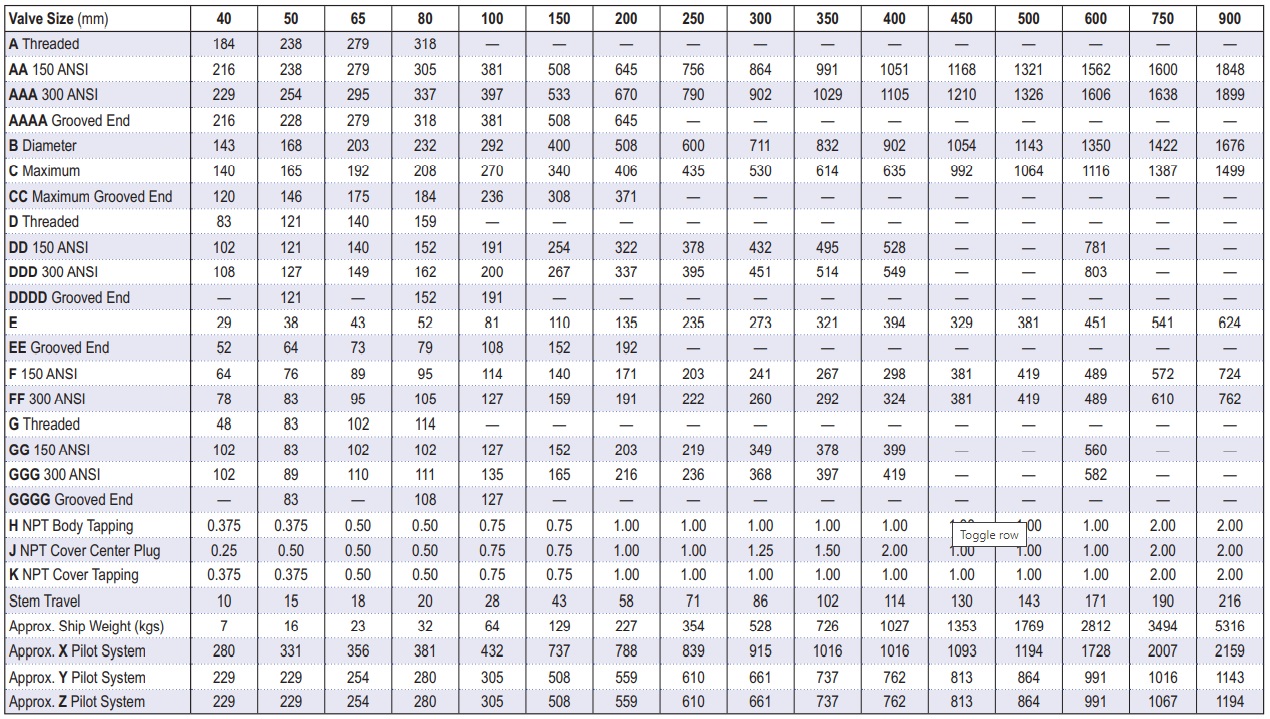
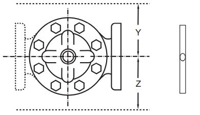
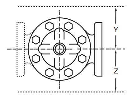
Pilot System Specifications
Adjustment Range
Low flow equals one-fourth of maximum flow stated in the X52E Orifice Plate bore chart.
See X52E Engineering Data Sheet for orifice bore chart for suggested flow rates.
Temperature Range
Water: to 180°F
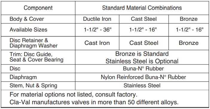
Materials
Standard Pilot System Materials
Pilot Control: Low Lead Bronze
Trim: Stainless Steel 303
Orifice Plate: Stainless Steel 303
Rubber: Buna-N® Synthetic Rubber
Optional Pilot System Materials
Pilot systems are available with optional
Aluminum, Stainless Steel or Monel.
X52E Orifice Plate Assembly Data
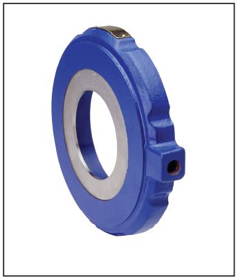
- Wafer Design
- Fits ANSI 125, 150, 250, 300
- Orifice Plate portion of assembly is made of 302 Stainless Steel
- Optional Materials Available
- See X52E Engineering Data Sheet for Bore Sizing Selections Chart (E-X52E
When Ordering, Please Specify
- Catalog No. 40-01
- Valve Size
- Pattern – Globe or Angle
- Pressure Class
- Threaded or Flanged
- Trim Material
- Adjustment Range/Orifice Bore
- Desired Options
- When Vertically Installed
Note: Orifice plate assembly (X52E) may be attached to the main valve outlet flange, however, better control is obtained if it is located one to five pipe diameters downstream.
Orifice plate sensing connection should be located in the pipeline on the side of the orifice plate assembly. The orifice plate assembly should not be mounted directly to a butterfly valve. See E-X52E Data Sheet for Orifice Bore adjustment range.